In the wake of my previous teardowns of the iPhone 4 and 4S batteries, I went onto eBay and Amazon (realizing that they finally have Amazon Prime student rates up in Canada) and bought a few iPhone 5 and 5S batteries. Although I was primarily interested in trying to get the gas gauge information out of the batteries, I had a secondary reason. The Nexxtech Slim Power Bank (a subject of a separate blog post) uses a pair of 3.8-volt Li-ion polymer batteries, and they seemed to be be suspiciously similar in size to what is used in the iPhone 5. But enough of that, we’re here for the iPhone 5 battery in particular!
Battery Casing


The iPhone 5 battery measures 3.7 mm in thickness, 3.2 cm in width and 9.1 cm in length. This particular model, made by Sony, has a model ID of US373291H, with the six digits corresponding to the cell’s dimensions. This cell has a labeled capacity of 1440 mAh at a nominal 3.8 volts, with a maximum charge voltage of 4.3 volts. I tried to read the data matrix barcode on the cell but my barcode scanning app on my phone refused to recognize it. I might try to scan and sharpen the barcode later but it’s not something that’s of a high priority to me.
Battery Teardown and Pinout
The board itself is rather interesting. The protection MOSFETs used to switch the battery’s power are chip-scale packages and are glued down with epoxy, same with the gas gauge itself. This means that I can’t easily replace it with a rework station if the need arises. The board includes the gas gauge, thermistors, protection circuitry and still has room for a polyfuse for extra over-current protection.
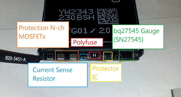
iPhone 5 battery PCB layout
The pinout of the iPhone 5 battery is pretty much the same as of the iPhone 4 and 4S. You have Pack-, NTC Thermistor, HDQ and Pack+. In this particular model of battery, the gas gauge is a bq27545 (labeled SN27545), but has basically the same feature set as the iPhone 4/4S’ bq27541. With this information, I soldered to the small terminals on the connector (the actual connectors for this battery haven’t arrived yet since it takes so long to receive items from China on eBay), and hooked it up to my trusty Texas Instruments EV2400 box.

iPhone 5 battery pinout
Battery Data
 And once again, we’re presented with an obscure firmware revision. The latest bq27545-G1 firmware is only version 2.24, but this chip has version 3.10. After forcing GaugeStudio to accept this gauge as a -G1 version, we’re once again presented with a sealed chip. Let’s try to unseal it with the default key…

Nope. No dice with 0x36720414, unlike last time.
… and I get the dreaded “Unseal Key” prompt. Cue the dramatic Darth Vader “NOOOOO” here. Maybe Apple read my previous post and decided to change the default keys this time (Hey Apple, if you read this, make the iPhone 6’s gas gauge have the default keys again)! This means that not only can I not access any of the juicy details of this battery, but I cannot update its firmware to a more… conventional version either. I could try brute-forcing it, but trying to hack a key with a 32-bit address space over a 7 kbps bus… uh, no. That’s not going to happen. I’d probably have better luck reverse-engineering Apple’s battery code but I doubt they have any facility to do in-system firmware updates for the gas gauge.

Data captured from GaugeStudio
Now for some rather… interesting details of what we can access. The design capacity of this battery, according to the gas gauge, is 1430 mAh, same as the iPhone 4S and also 100 mAh less than what’s written on the label. That, and the full charge capacity of this battery is 1397 mAh out of the gate. The gauge seems to be an insomniac (it won’t enter Sleep mode even when the battery is not hooked up to any load), and it seems to have less features despite having a higher firmware version (I’m sure the internal temperature isn’t 131 degrees C…), and the Pack Configuration register doesn’t bring up any sensible data.
Battery… conspiracy?
One thing that I haven’t confirmed is whether or not this battery had been tampered with before I received it. I bought this particular battery from eBay and it was listed as new. It had some adhesive residue but no obvious sign of being peeled off from another iPhone. The cycle count is set to 1, and because the gas gauge is sealed, I can’t read any other data like the lifetime data logs. There is a chance that this battery isn’t new and that the seller had somehow changed the data memory and sealed the chip with a non-default key, but I need to wait until some other batteries arrive in the mail and perhaps try reading out batteries taken out directly from some iPhone 5s. Until then, it’s only speculation as to why this chip is sealed with a different key.
The next victims specimens: an iPhone 5S battery, a “new” iPhone 4 battery, and an Amazon Kindle battery.

Pingback: So Phone Me Maybe: A list of iPhone batteries with gas gauge functionality | Rip It Apart – Jason's electronics blog-thingy
Hi Jason, interesting stuff!
I’d like to measure the power of the iphone 5 battery with the power monitor tool of moonson solutions. I managed to do that for an Android battery with some help from my mates. I’m not an expert in electronics.
I unwrapped the outer black protector of the battery and if you pull out the battery board a bit, you can find two plain silver threads attached to the board that sink into the battery itself. My question is: are those wires the + and – polarity points so I can connect the power monitor measurement tweezers there? Or it’s the two golden dots at the further side in the rear of the board instead? (let me know where i can attach some screenshots if needed)
The reason to try to do this is that the way the battery is connected to the device doesn’t allow me to manipulate the polarity points as easily as explained in page 43 at http://msoon.github.io/powermonitor/PowerTool/doc/Power%20Monitor%20Manual.pdf
I’ve checked on the internet but i can’t find any diagram.
Thanks in advance!
LikeLike
The two gold test pads on the end of the PCB are for factory programming of the fuel gauge, and the two large silver leads are the cell’s positive and negative terminals. (See diagram here: http://puu.sh/eefAV/d5c81e37aa.png)
The iPhone battery will be more challenging than the battery procedures outlined in the PDF manual you linked. The fuel gauge is used by the iPhone to measure its power use and also provide state of charge information, and you will likely need to detach the Li-Ion cell from the fuel gauge PCB entirely in order to hook it up to your power analyzer. I’d recommend setting the power supply to 4.2-4.3 volts initially and waiting a few seconds for the fuel gauge to attempt to get an open-circuit voltage measurement. The gauge will be rather unhappy about being hooked up to a power supply instead of a Li-ion cell, but it will at least allow in-circuit measurement of the iPhone’s power consumption.
As a word of caution, those cell terminals are *unfused* and any short circuit that occurs could cause some serious damage to your battery, your workspace and possibly yourself. Use a temperature-regulated soldering iron, use flux on the terminals to assist removal and work quickly so the PCB and cell tabs won’t be heated too much.
LikeLike
Thanks for your detailed explanations Jason, it is now more clear to me on how to proceed. I’ll be very cautious with this, thanks for the warning. I’ll let you know how it goes!
LikeLike
Hi again Jason, just one quick question.
When you exposed the iPhone5 battery PCB layout, did you applied any sealing so the battery doesn’t have any hole where the gas can escape? I ask this because I connected copper tape to the cell+, and as soon as i did the same for the cell-, there escaped some smoke from the battery (which was connected to the iPhone and with the iPhone turned on, I didn’t have the copper tapes connected to the Power Monitor yet).
On the photo you send there looks like a kind of grey foam sealing the battery http://puu.sh/eefAV/d5c81e37aa.png
Or maybe there’s a way to expose the PCB layout without making any crack on the upper part of the body of the battery?
Thanks!
LikeLike
The foam tape was there to begin with; it’s just used as a bit of a cushion for the PCB.
Laminate/pouch cells don’t have any means of venting gas (they just puff up like a balloon). In your case, if your battery started smoking when hooked up, then something has gone really, really wrong with your setup. Were you using the original Li-ion cell in your setup, or are you using an external power supply? On that note, you didn’t happen to short Cell+ to Cell-, right?
If possible, could you send me some pictures of your setup? I may be able to assist you further if I am able to see how your setup is configured.
LikeLike
Hi Jason, I attach the link of some ss.
https://drive.google.com/a/king.com/#folders/0BxTnSksTUMd5UEFoY2Z6NVFLcGs
https://drive.google.com/a/king.com/#folders/0BxTnSksTUMd5UEFoY2Z6NVFLcGs
https://drive.google.com/a/king.com/#folders/0BxTnSksTUMd5UEFoY2Z6NVFLcGs
What I basically did was adding a couple of copper tape strips on the poles to connect them to the Power Monitor hooks. On previous tries before that battery puffed up, the power Monitor detected that “something” was connected, (i don’t know if the battery or the phone too). When I set up the voltage (to 4.2V as you said, i also waited a long time to be sure the connection was stablished) and hit on Vout Enable button, the PM didn’t detect any current from the copper tapes. Notice that below the + connection of the battery I put Kapton tape as stated in page 45 on the Power Monitor manual to replicate the same proces as on Android.
Before trying this last failed configuration, I attached 4 thin copper tapes for each pinout on the device (it was very difficult to avoid them touch each other but I achieved it , On this config, I also attached 4 thin copper tapes to the battery connectors, so the battery was outside the iPhone. The question remains if maybe there wasn’t enough contact surface on the 8 thin copper tapes to transmit the current.
I ordered some TEST CLIP SET FLUKE AC283 and TL222 cable leads to attached them to each battery pin of the device to ensure there’s a good connection.
I just wanted to remind you that i’m an ignorant regarding electronics, if something wasn’t clear let me know.
Thanks for your help!
LikeLike
Your Google Drive links aren’t working for me; it’s throwing a permissions error of some sort.
You shouldn’t really even need the Li-ion cell to do measurements, if you’re hooking up to Cell+ and Cell- on the PCB itself. In the case of the Power Meter documentation, the use of the Li-ion battery packs are more as a “spacer” to allow an electrical connection to the battery contacts.
LikeLike
Hi Jason,
Sorry for the delay in answering back. We did as you said, we soldered to the pins on the PCB and now it works seamlessly! without your help we would still be trying weird things probably! many thanks again for your clear explanations =)
LikeLike
Glad to help! :3
LikeLike
I just wanted to add that we still tried another configuration. This worked for some minutes and the iPhone died. We soldered directly to the battery pins in the device, also the ones in the battery itself. The cable we used wasn’t the typical copper one with 20-30 tiny threads. it was an aluminium one instead. We managed to get some metrics but some soldering points broke, and with them some pins were ripped off from the device pinout. Also, as imagined, soldering on the pad of the battery itself melted the plastic surrounding the pins… actually in the end only the 4 spots on the surface of the pad were left… curiously, it’s when one those silverish 4 spots only remained that the metrics worked for some minutes. The soldering iron was not temperature regulated so i can imagine that we also might have affected some tiny components.
LikeLike
Hi Jason,
I was really impressed that you were able to read out the battery chip.
We are looking for a simple solution to read out chip for quality control.
Would be great if you could sent me a mail for more details.
Best regards,
Fred
LikeLike
Hi Fred,
In one of my blog posts I published some software that uses a PC’s serial port to read out HDQ-equipped fuel gauges. (see https://ripitapart.wordpress.com/2014/09/30/reading-out-hdq-equipped-battery-fuel-gauges-with-a-serial-port/ ) As for I2C gauges (TI’s gauges are I2C by default and are made into HDQ gauges during the factor programming process), that was done with TI’s EV2400 adapter (sadly it costs $200 when it used to cost me $50 several years back) but occasionally the older EV2300 can be purchased for much less than that.
If you are interested in the source code, I can email a copy to you, with the email address that you submitted when you posted a comment on my blog.
Jason
LikeLike
Pingback: Using Monsoon Power Monitor with iPhone 5s | Bottle of Code : Luke Hines