As seen on Hackaday!
If you haven’t heard of Power over Ethernet, chances are you’ve experienced its usefulness without even knowing about it. Power over Ethernet (PoE for short) does exactly as the name implies: power is sent over the same Ethernet cable normally used for data transfer. This is often used for devices like IP phones and wireless access points (often you see these APs in restaurants and other establishments mounted to the ceiling to provide Wi-Fi access), as it is far easier, cheaper and safer to provide low-voltage power instead of wiring in AC power which requires the help of a licenced electrician.
-
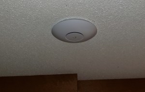
- My ceiling-mounted Ubiquiti UAP-AC-PRO Wi-Fi access point, a typical use case for Power over Ethernet
A (Very Simplified) Background on Power over Ethernet
The actual PoE standards (click here to learn more) IEEE-802.3af (up to 12.95 watts), 802.3at (up to 25.5 watts) and the newest 802.3bt (up to 60-90 watts) standards provide vendor-independent methods for sending and receiving 48-volt DC power over the Ethernet cable without frying the device on the other end if it’s not equipped to receive power. The PSE (power sourcing equipment) manipulates the Ethernet pairs to sense the presence of a PD (powered device), then queries what power level it should provide; after this negotiation phase, the PSE finally sends 48 volts to the PD (usually on pins 1/2 and 3/6, called Alternative or Mode A) and all is merry, thanks to the help of “phantom power“. However, cheaper devices are available which skip this and simply shove DC power over the Ethernet cable with no regard to the safety or well-being of the remote device – this is called “passive PoE”. There are no regulations regarding passive PoE, but they generally send DC power (often 12, 24 or 48 volts) over Ethernet pins 4/5 and 7/8 (called Alternative or Mode B), usually shorting the two pins on each pair for easy power transmission at the expense of being limited to 10/100 Mbps speed.
Many years ago (I’m talking back in high school, over 6 years ago), I bought some cheap PoE equipment – a D-Link DWL-P200 PoE injector and splitter kit – assuming it was compatible with 802.3af due to its use of 48 volts… it wasn’t. Since I bought this on a trip to the US and I live up in (the arguably nicer 🙂 ) Canada, I couldn’t be bothered attempting to return it to the Fry’s that I bought it from; it served some use powering a wireless router for a few years before I ditched it in favour of a ZyXEL GS1920HP-48HP 802.3at-compatible switch and Ubiquiti UAP-AC-PRO access point. It then sat in my junk bin for a while before I took it back out and conjured up a solution to make the splitter compatible with the PoE standard; this way I could tap into my existing 802.3at-compatible infrastructure I wired into my house (or perhaps use it to siphon a couple watts in other places 🙂 ).
Note I am using the word “compatible” and not “compliant” since this definitely does not attempt to comply with all of the electrical specifications contained in the 802.3af/at standards; however, I have tested this on 802.3af and 802.3at Ethernet switches and have had no issues with the upgraded splitter. One significant attribute is that true PoE requires electrical isolation and my splitter certainly does not provide it; for my use this isn’t an issue and even some commercial splitters omit this feature to reduce cost.
Modifying the D-Link DWL-P200 for 802.3at Compatibility
-
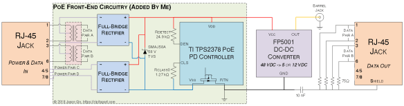
- Block/circuit diagram for the upgrades performed on the DWL-P200 PoE splitter
The DWL-P200 is a near-ideal candidate for conversion to 802.3af/at (I’ll call it “active PoE” from now on) since it already uses 48 volts for power – all it really needs is an active PoE-compatible front-end which requires an Ethernet isolation transformer, two diode bridges, a TVS (transient voltage suppression) diode, a 802.3af PD controller chip (and a partridge in a pear tree?). Easy enough, right… right?
Step 1: Prepare the Power Interface
The DWL-P200 splitter does not use a diode bridge on its power input (pins 4/5 are positive and pins 7/8 are negative), but active PoE requires that PDs include diode bridges for polarity-insensitive operation. Additionally, the splitter does not have an isolation transformer normally used for Ethernet; rather it had 10 ohm resistors on pins 1/2 and 3/6 as series coupling between the input and output – these were removed to provide a spot to install the centre-tapped isolation transformer that active PoE requires for Mode A (power on pins 1/2 and 3/6).
After harvesting an Ethernet transformer from a dead MacBook (seriously, dead computers make for great component stores), I scraped away insulation on the differential data pairs and used 40-gauge magnet wire to connect each pair to the transformer, and used 30-gauge Kynar wire for the power lines which are connected to the centre tap of each pair. To affix it, I used a blob of hot glue (which turned out to be pretty useless since this board runs HOT!), and ran the wires off to one of the diode bridges in the front-end I built.
The data output pins (1, 2, 3 and 6) are terminated to an AC-coupled ground using 75 ohm resistors, often referred to as “Bob Smith termination” to help reduce noise.
Step 2: Build the PoE PD Front-End
The actual front-end was built as two separate boards: the first was the power input board; the second was the 802.3af active PoE PD controller, which had its own construction considerations that I’ll address in a bit.
-
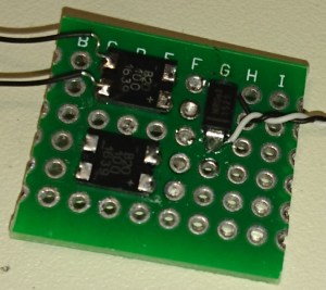
- Power input board for the PoE splitter mod. Uses two 60 volt Schottky diode bridges and a SMAJ58A TVS diode for overvoltage protection
The power input board is pretty simple and was comprised of two Bourns CD-HD201 60-volt Schottky diode bridges and a SMAJ58A 58-volt TVS surge suppression diode to help overcome voltage spikes that can occur when a cable is unplugged due to the inductance in the cable itself. The inputs of the diode bridges were then connected to the centre taps of the Ethernet transformers and the original pins 4/5 and 7/8 on the power/data input of the splitter.
-
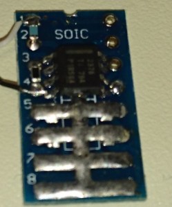
- Texas Instruments TPS2378 PoE PD controller on DipMicro SOIC-to-DIP adapter. Note the heatsink fins added to the board
The second board is the PoE PD controller, which is responsible for negotiating with the 802.3af/at PSE controller at the other end of the cable. I used the Texas Instruments TPS2378 PoE PD controller, which was meant for 802.3at Class 4 (25.5 watts maximum) but I’m only using it for 802.3af Class 0 (up to 12.95 watts). The TPS2378 has a heat-sinking “PowerPAD” on the bottom which must be connected to Vss (ground); I used solar cell tabbing wire underneath and created a sort of fin-like arrangement on the unused area of the DipMicro SOIC/TSSOP-to-DIP adapter board (they don’t sponsor me – I just really like their adapter boards!). The external PoE detection and power class signal resistors were soldered to the DIP pads on the adapter to save space.
Step 3: Put it Back Together Again
-
- Power input and PoE PD controller boards nestled inside original case. Note the added Ethernet isolation transformer next to the RJ-45 jack on the right.
-
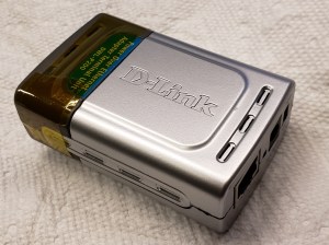
- Reassembled PoE splitter
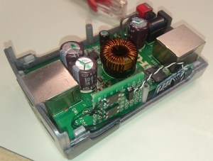
Once the two boards were assembled and connected to the original FP5001 DC-DC converter‘s input, the boards were nestled inside the original case and some Kapton tape was wrapped around the case since I damaged some of the plastic clips that held it together during disassembly.
Conclusion
With the active PoE upgrades installed, the splitter now works with 802.3af, 802.3at and passive 48 volt PoE power sources. However, the internal construction of the splitter means it only supports 10/100 Mbps Ethernet. Additionally, I find that the board gets very hot under full load (I’ve measured internal temperatures well above 100 degrees C when the case is closed) which negatively impacts its efficiency, but I consider it a fair trade-off considering this was never meant to work on active PoE in the first place.

Pingback: Power Over Ethernet Splitter Improves Negotiating Skills | Hackaday
Pingback: Power Over Ethernet Splitter Improves Negotiating Skills - itmix.cz | Informační Náskok
Thank you for this blog post, i was trying to confirm my suspicion that this adapter set was passive poe.
LikeLike