Since my previous attempts at getting the Motorola smart cards to work were generally fruitless, I decided to revive an old attempt to get a TI-83 Plus LCD screen to work by itself. Earlier tries failed due to mistakes in creating a pinout for the LCD, and at one point I thought I damaged the driver as the chip got very hot.
After completing a recent assignment for my electronics engineering class involving the classic 8-bit parallel HD44780 LCD (and finally understanding the difference between 8080 and 6800-type parallel interfacing), I dug up a datasheet for the LCD and spent about an hour and a half getting it to display content.
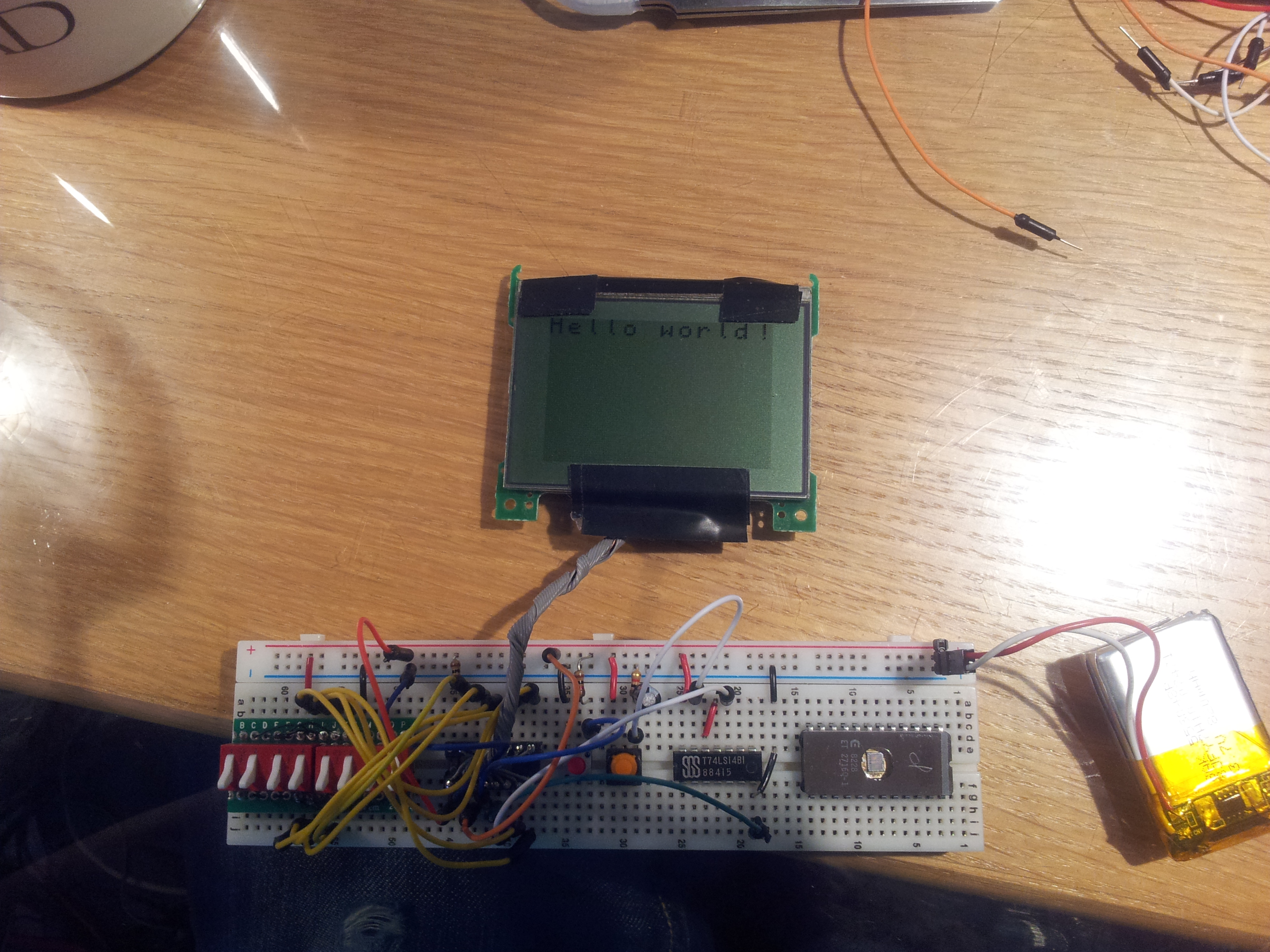
… And it worked! Because this LCD is a graphic LCD, there is no built-in method to display text. For my tests I manually entered the command and graphic data, by hand, using nothing more than a bank of DIP switches and a debounced pushbutton.
The LCD, when first initialized, has complete garbage in the built-in display SRAM. I had to manually enter 0s for all the visible pixels on screen in order to clean up the display, then set the rows and columns manually to print out “Hello world!” on-screen.
The LCD driver is a Toshiba T6K04, which has 128×64 resolution internally but only the left 96 pixels are visible on the screen. It uses an 8-bit 6800-type parallel interface (CE is used for clocking in data) and, depending on the age of the calculator, has all the support circuitry on the same PCB.
Note that newer TI-83 Plus models are built a lot “cheaper” than the older models. The newer ones don’t have a PCB on the back of the LCD screen and all the support components are on the mainboard. I had one that was made around 2004, give or take a couple years. There are older models that use the Toshiba T6A04. I believe the pinout for the older TI-83s using the T6A04 is different, but the command set is the same.
For the ~2004 era of TI-83 Plus calculators, the pinout is as follows:
- Reset: Active-low input for resetting the LCD screen.
- D0: Input for the 8-bit parallel interface
- D1: Input for the 8-bit parallel interface
- D2: Input for the 8-bit parallel interface
- D3: Input for the 8-bit parallel interface
- D4: Input for the 8-bit parallel interface
- D5: Input for the 8-bit parallel interface
- D6: Input for the 8-bit parallel interface
- D7: Input for the 8-bit parallel interface
- CE: Active-low clock for the parallel interface
- RW: Input for parallel interface read/write mode: High = read, low = write. For most purposes you can leave this tied low.
- D/I: Selects whether to send graphic data, or to send a command. High = data, low = command.
- STB: Active-low standby input. Typically you would leave this tied high unless you want to put the LCD in a low-power state.
- NC: Bare pad that is not connected to anything on the PCB.
- NC: Bare pad that is not connected to anything on the PCB.
- VCC: Power supply input: 2.7-5.5 volts DC.
- GND: Power supply ground.
After a bit of tinkering I’ve created a table of commands to send to the LCD to initialize it.
|
D/¬I |
R/¬W |
D7 |
D6 |
D5 |
D4 |
D3 |
D2 |
D1 |
D0 |
Action |
|
0 |
0 |
0 |
0 |
0 |
0 |
0 |
0 |
0 |
1 |
Set 8 bit mode |
|
0 |
0 |
0 |
0 |
0 |
0 |
0 |
0 |
1 |
1 |
Enable display |
|
0 |
0 |
1 |
1 |
x |
x |
x |
x |
x |
x |
Set contrast (0bxxxxxx) |
|
0 |
0 |
0 |
0 |
0 |
0 |
0 |
1 |
0 |
1 |
Sets counter mode: 8 bits along X, each write increases row # by 1 |
|
0 |
0 |
0 |
1 |
c |
c |
c |
c |
c |
c |
Set column (0bcccccc), display driver is 128×64 but left 96 columns are visible |
|
0 |
0 |
1 |
0 |
r |
r |
r |
r |
r |
r |
Set row (0brrrrrr) |
|
1 |
0 |
d |
d |
d |
d |
d |
d |
d |
d |
Write display data (8 bits wide) |
If time permits (and after college midterms are over, etc.) I’ll write up a quick microcontroller program to control the LCD.
