(UPDATE: March 2, 2015 – I’ve picked up a pair of the newer tamper-resistant versions of this wall outlet. A review and teardown on that unit is coming up; stay tuned!)
(UPDATE 2: May 29, 2016 – Scratch that on the first tamper-resistant model; it had the same performance as the one mentioned here. Also, Costco has released a 3.1A version of this outlet, and is currently under review.)
About a week ago I bought a set of wall outlets from Costco that integrate two USB charging ports into a standard Decora-type receptacle. It’s marketed to replace your traditional AC adapter, allowing other appliances to be plugged in while charging your portable electronics.
-

- Front of packaging
-

- Back of packaging
The outlet is made by Omee Electrical Company, but curiously enough this particular model, the OM-USBII, wasn’t listed on their site. The packaging itself bears the name Charging Essentials, with a logo that looks like a USB icon that’s had one Viagra too many. The packaging states that the outlet has:
- “Two 5VDC 2.1A ports for more efficient charging in less time”
- “Smarter USB charging with special chip designed to recognize and optimize the charging requirements of your device”
- “Screw-free wall plate snaps into place for a more clean, modern appearance”
The second note is of particular importance to me. If it’s true, that means it might be using some USB charge port controller like TI’s TPS251x-series chips. But I’m not one to have blind faith in what’s written on the packaging. Let’s rip this sucker apart!
-

- Front of outlet
-

- Side view
-

- Mounting flange – note lack of screw threads
The outlet has a snap-on coverplate which may look sleek but could hamper removal of this outlet later on if needed. I was curious as to why one couldn’t just use a regular screw-on coverplate, and it turns out it’s because the mounting flange doesn’t have any tapped screw holes; you physically can’t use screws on this because the manufacturer didn’t want to go to the effort to make holes that can accept screws!
The casing is held together with four triangle-head screws in a weak attempt to prevent opening of the device. I had a security bit set on hand so this posed no hindrance to me. Upon removing the cover, the outlet seems rather well built. However, after removing the main outlet portion to reveal the AC-DC adapter inside, I quickly rescinded that thought.
-

- Front cover removed
-

- AC-DC converter
-

- Back side of PCB – note lack of isolation between both halves
-

- Top side of PCB
-

- Samxon brand capacitor
The converter seems relatively well-built (at least relative to some crap Chinese power supplies out there). Some thought was put into the safe operation of this device, but there’s almost no isolation between the high and low voltage sides, and the DC side of this adapter is not grounded; the “ground” for the USB ports floats at 60 volts AC with respect to the mains earth pin. The Samxon brand caps are also pretty disappointing.
As for the USB portion of this device, I had to remove some hot glue holding the panel in place. After a few minutes of picking away at the rubbery blob, I was able to pull out the USB ports.
-

- Back of USB ports – no charge port controller in sight
… and I found LIES! DIRTY LIES! There is no USB charge port controller, contrary to what the packaging claims. It just uses a set of voltage dividers to emulate the Apple charger standard, which could break compatibility with some smartphones. Ugh, well let’s put it back together and take a look at it from the performance side of things. At least the USB ports feel pretty solid…
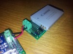
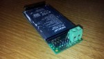
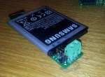
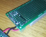
To measure the voltage-current characteristic of the outlet, I rebuilt my bq27510-G3 Li-Ion gas gauge board so it had better handling of high current without affecting my current and voltage measurements. The reason I used this is because the gauge combines a voltmeter and ammeter in one chip, and by using the GaugeStudio software, I could create easy, breezy, beautiful V-I graphs.
-

- Outlet installed in a plastic box to avoid in-wall installation
-

- bq27510 board and Re:load 2 as testing apparatus
Using a Re:load 2 constant-current load, I slowly ramped up the load current while logging the voltage and current data to a CSV file for analysis in Excel.
 This charger’s… okay. It has surprisingly good regulation up to 2.3 amps, but after that point the AC-DC converter basically brickwalls and the voltage plummets to 3 volts. That said, this also means that this outlet is not a set of “two 2.1A USB ports”. You can charge one tablet but you won’t be able to charge a tablet along with another device simultaneously.
Bah, I’ve had it with this wall outlet. Looks like this one’s gonna be returned to Costco in the next few days. This outlet may be adequate for some people, but for me it’s a disappointment.
Pros:
- Solid USB ports
- Good voltage stability (up to 2.3 amps, enough to charge ONE tablet)
- Apple device compatibility
Cons:
- Annoying coverplate design
- Does not meet rated current output, will not charge 2 tablets or 1 tablet + another device
- Does NOT have a “smart charging chip” despite being stated on packaging, some devices (eg. BlackBerry) will refuse to charge from these ports
- Power supply for USB seems cheap
- USB port is not grounded – if a short-circuit happens inside the power supply it can be a shock hazard to you