Considering how popular the iPhone is, there’s always going to be some counterfeits out there. I’ve been out buying various iPhone batteries to build a database of each generation’s characteristics, but one model has eluded me so far: the iPhone 5S. The iPhone 5C’s battery that I bought appears to be genuine (but with its own issues), but none of the iPhone 5S batteries I’ve bought so far (4 of them at the time of writing this blog post) were genuine. All of these fakes look like a genuine battery at first glance, but all of them share a few common traits.
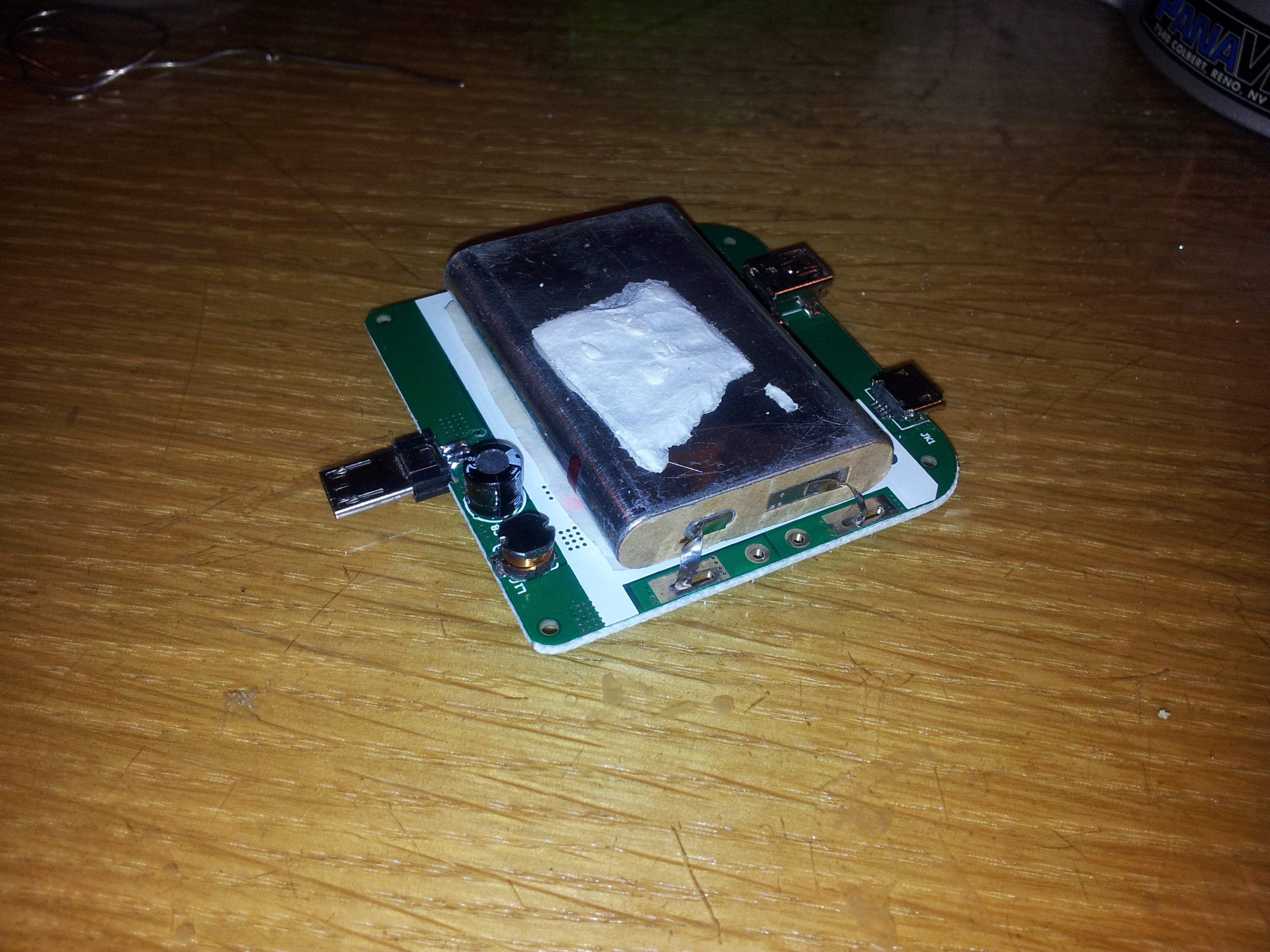
Battery teardown
-

- Label with parameters listed
-
- Other side of label
The fake battery sports the usual iPhone battery information, complete with some dot-matrix printed data and a data-matrix barcode. It’s labeled with a capacity of 1560 mAh and 3.8 volts nominal voltage.

Comparison between real and fake iPhone 5S battery
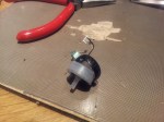
The connector itself has two points for soldering the connector to provide durability. However, with the fake batteries, they are not soldered down. The two spots on the ends of the connectors are dark with a small point visible inside it (that point is the reinforcement pin on the connector). If this connector is installed in an iPhone, it will probably not come out without either damaging the battery’s connector, or worse, leave the plastic connector piece inside the phone, requiring tweezers to remove.

Connector lifted off with a hobby knife
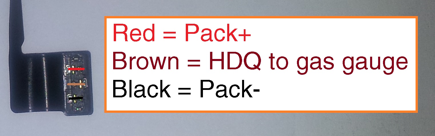
iPhone 5S and 5C battery pinout
Removing the black protective tape reveals an iPhone 4 battery fuel gauge board. The connector is soldered to this board, with four solder points visible.

iPhone 4 battery PCB with soldered-on flat flex connector
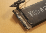
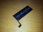
Pulling out the PCB reveals another characteristic of these fake batteries: the positive terminal is cut short, with another metal section being clumsily spot-welded to the stub on the cell.

Note how the battery tab is poorly welded to the PCB.
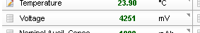
Battery fuel gauge data
The battery fuel gauge requires proper programming to accurately indicate the battery’s charge status. Because of this, each iPhone battery generation has its own specific configuration.
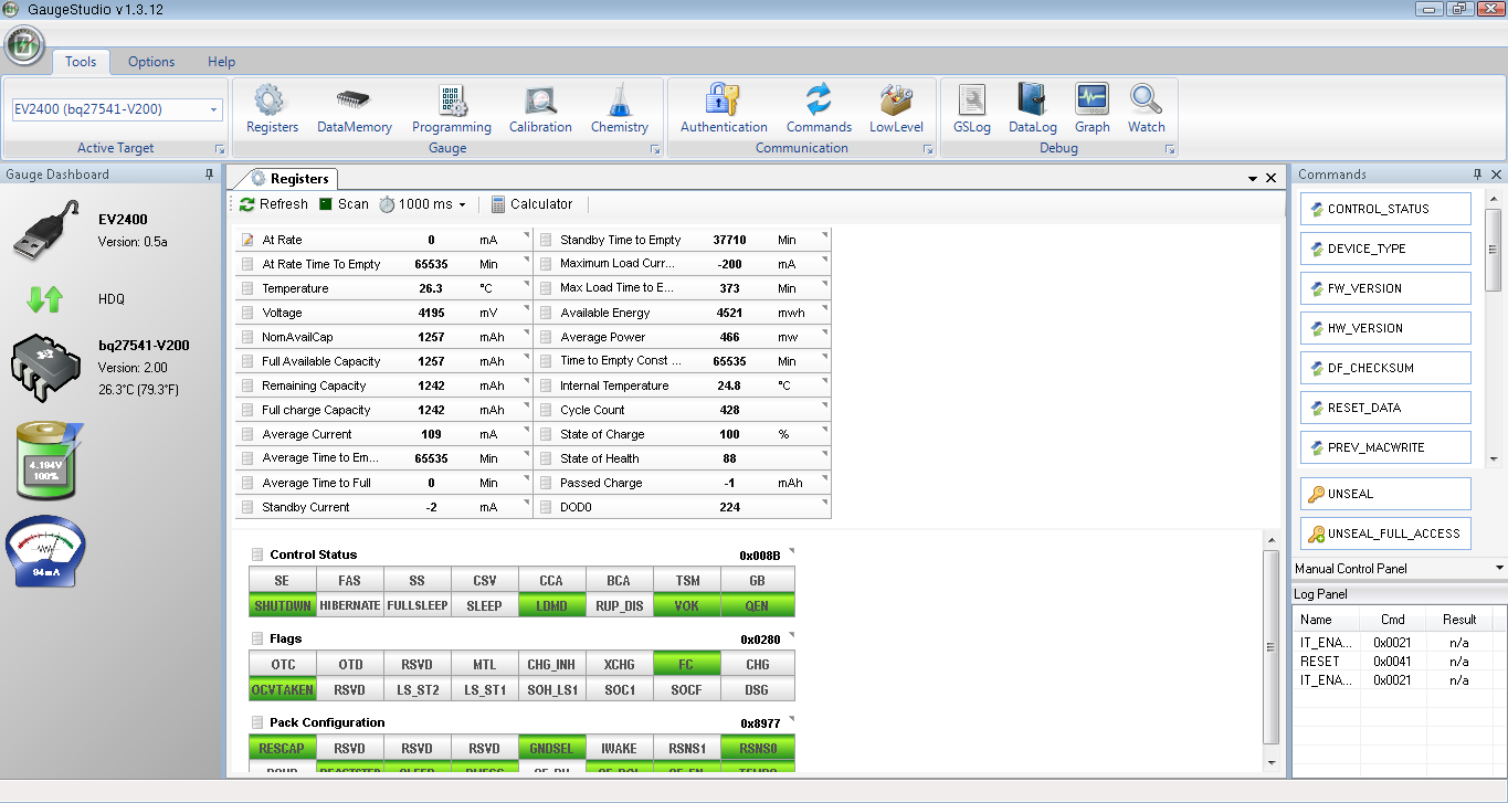
The fake iPhone battery retains the programming for the iPhone 4’s battery, which is a designed capacity of 1420 mAh, using a bq27541 fuel gauge running version 1.25 firmware. The data inside it is often that of a used/recycled battery as well.
This data can be (partially) read out directly from the iPhone with a tool such as iBackupBot, but more data can be read if the battery is read with another tool. I have the EV2400 from Texas Instruments to read this out on a PC, but this data can be read out with a USB-to-TTL serial port, a logic gate (a logic inverter) and a small MOSFET transistor.
I created a small tool that uses this circuit to interface with the fuel gauge and read out its data. Check it out here.
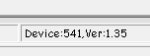
Using my tool, this is the report for one of these fake batteries. Note how it is identified as an iPhone 4 battery. Don’t be fooled by the calculated state of health. It’s not accurate for this battery as the fuel gauge still thinks it’s still inside an iPhone 4 battery pack.
**** START OF HDQ BATTERY LOG REPORT ****
HDQ Gas Gauge Readout Tool version 0.9 by Jason Gin
Date: 9/30/2014
Time: 0:52:24
Serial port: COM26

Battery Identification
========================
DEVICE_TYPE = 0x0541, FW_VERSION = 0x0125, DESIGN_CAPACITY = 1420 mAh
Battery's configuration matches that of a standard iPhone 4 battery.

Basic Battery Information
===========================
Device = bq27541 v.1.25, hardware rev. 0x00B5, data-flash rev. 0x0000
Voltage = 3804 mV
Current = 0 mA
Power = 0 mW
State of charge = 45%
Reported state of health = 0%
Calculated state of health = 99.3%
Cycle count = 14 times
Time to empty = N/A (not discharging)
Temperature = 27.9 °C (80.3 °F) (3009 raw)
Designed capacity = 1420 mAh
Heavy load capacity = 628/1410 mAh
Light load capacity = 673/1455 mAh

Advanced Battery Information
==============================
Capacity discharged = 0 mAh
Depth of discharge at last OCV update = ~778 mAh (8768 raw)
Maximum load current = -200 mA
Impedance Track chemistry ID = 0x0163
Reset count = 11 times

Flags = 0x0180
Flag interpretation:
* Fast charging allowed
* Good OCV measurement taken
* Not discharging

Control Status = 0x6219
Control Status interpretation:
* SEALED security state
* SLEEP power mode
* Constant-power gauging
* Qmax update voltage NOT OK (Or in relax mode)
* Impedance Track enabled

Pack Configuration = 0x8931
Pack Configuration interpretation:
* No-load reserve capacity compensation enabled
* IWAKE, RSNS1, RSNS0 = 0x1
* SLEEP mode enabled
* Remaining Capacity is forced to Full Charge Capacity at end of charge
* Temperature sensor: External thermistor

Device name length = 7 bytes
Device name: bq27541

**** END OF HDQ BATTERY LOG REPORT ****