PPS For All: Directly charging lithium-ion batteries with a USB-C PD tester

TL;DR – USB-C with PPS (Programmable Power Supply) technology is here, it’s cool, and now it’s usable on more than just the newest smartphones – it works on almost any Li-ion battery with the right USB-C tester. Check out the GitHub repo – it’s open-source!

As seen on Hackaday!

DISCLAIMER: Lithium-ion batteries can be dangerous if mishandled or abused! While much testing and development has resulted in a fairly stable implementation, this application is still an “off-label” use of a USB PD charger and USB-C tester, and therefore there is a risk of property damage, personal injury, or other unforeseen consequences if something goes wrong (and I will NOT be held responsible for that!).

Introduction

The USB PD (Power Delivery) standard has revolutionized how we charge our everyday electronic devices. While many new devices (such as smartphones) emphasize “fast charge” capability, it has required changes to both the device itself, as well as the adapters that power them.

Because power losses in the charging cable (or any other resistance) is directly related to the amount of current flowing through it, one can get more power for the same amount of current by increasing the voltage (this is how the AC power transmission lines that you see on the street and countryside work as well). The USB PD standard allows a device to request the adapter to increase its output voltage from 5 volts to a higher level, such as 9, 15, or 20 (and sometimes 12) volts.

An addition in the third version of the USB PD standard added optional PPS (Programmable Power Supply) support for the power adapter, which allows an adapter to output a wide range of voltages, rather than a fixed “menu” of 5, 9, 15, 20 (and sometimes 12) volts.

What is USB-C PPS charging?

PPS charging is a relatively new variation to the existing PD charging scheme. It allows the device being charged to actively communicate with the adapter and request a precise voltage (and current) level, increasing efficiency since DC-DC conversion efficiency drops when the difference in voltage between the input (the adapter) and output (the battery) is larger. With this bidirectional communication, it allows the adapter to share some of the regulation workload, and therefore move some of the heat-generating power conversion to the adapter, allowing the device’s battery to charge at a cooler temperature which improves its lifespan.

Direct Battery Charging

One step past normal PPS charging is direct charging, which completely offloads the power management to the adapter; the host device controls the charge process purely via software commands to the adapter. This is analogous to the DC fast charging method used in electric vehicles (EVs), which also perform all power regulation outside of the vehicle and its internal charge circuitry. Because the device no longer needs to perform its own DC-DC conversion, this skips a step in the power conversion “chain”, increasing efficiency and reducing the amount of heat dissipated in the host device (you can’t lose power on a conversion step if you never perform that step in the first place!). With this reduction in internally-generated heat, the battery can be charged at even faster rates than it could with previous charging schemes.

One barrier to the widespread adoption of direct charging is that it requires the device to explicitly support it, as it requires significant changes to how the “power path” is designed internally. It also requires the adapter to support the voltage and current levels required by the host.

Diagrams comparing normal versus direct charging schemes.

Diagrams comparing normal versus direct charging schemes. (click here for full-size image)

Thankfully, on the adapter side, PPS support is becoming more and more common, even though most devices on the market (at least at the time of writing) don’t support it. However, because that potential is already present, perhaps there’s a way for the electronics hobbyist to take advantage of direct charging for their own batteries…

Shizuku Platform and its Lua API

The Shizuku USB multimeter by YK-Lab, which is available in a few rebadged forms under names like YK-Lab YK001, AVHzY CT-3, Power-Z KT002, or ATORCH UT18, is a very useful USB charger testing device. It features USB-A and USB-C ports; can measure voltage, current, power; can calculate passed charge (mAh) and energy (mWh) in real time; but unlike most USB testers on the market, it is user-programmable in Lua, a lightweight programming/scripting language.

The Lua API on the tester provides a large amount of extensibility beyond the original tester’s design, and in my case I’m using its ability to “trigger” non-standard voltages from fast-charge capable power adapters as well as its colour LCD screen to act as a highly flexible direct charger – an intermediate between a USB-C PD PPS adapter and an arbitrary (Li-ion) rechargeable battery.

Introducing: DingoCharge!

The idea behind making a battery charging script came about when I looked at using bench-top adjustable power supplies to charge batteries. Since the Shizuku tester (in my case, it was the AVHzy CT-3 variant) allows me to use the PPS protocol to finely adjust the adapter’s output voltage, I tried manually varying the voltage to increase or decrease the current flowing into a battery – and it worked!

That said, constantly checking the battery’s current and voltage levels just to charge a battery gets pretty tiring, and since the Shizuku is Lua-programmable… why not make a script that automates all of this for me? Thus began a programming journey that’s been ongoing for over a year, and I’ve still got ideas to add even more functionality (as long as I don’t crash the tester by running out of memory… don’t ask me how I know).

Charge Regulation Algorithm

All lithium-ion batteries (including less-common ones like lithium-iron phosphate (LiFePO4) and lithium titanate) use what’s known as CC-CV charging; this stands for constant-voltage/constant-current. A fixed amount of current is fed into the battery until its voltage reaches a certain threshold, then the voltage is held at a fixed value until the current going into the battery drops below another, lower, threshold. Once this is reached, the current is turned off entirely and the charge process is complete.

Although the PPS specification allows a device to set a maximum current level, my own testing revealed that there was too much variation amongst all my different adapters that I could not rely on the hardware to perform the constant-current regulation with enough precision for my liking, and the voltage drop across the USB-C cable resulted in the battery’s charge current tapering off too early as the voltage at the adapter reached its programmed constant-voltage level before the battery’s own voltage had a chance to do so as well. Instead, my charge algorithm increases the requested USB PD charge voltage above the battery’s own voltage until the desired current level is within a certain deadband range.

Once the target constant-voltage level is reached, the charge algorithm switches to constant-voltage regulation, maintaining a preset voltage until the current being drawn by the battery falls below the termination threshold.

If a battery was previously overdischarged, it requires a slower “precharge” current to bring the battery’s voltage up to a level that is safe for its regular charge current.

Charge Safety Tests

Over time, I added more safety checks to ensure that the battery’s state was maintained within a safe margin for voltage, current, temperature, and also time. If a safety violation was detected during charging, the charging algorithm would automatically set its charge current to zero, effectively terminating the charge process. Additionally, if the charge process was finished but a small current flowing into the battery resulted in the battery’s voltage getting too high, the PD request voltage gets adjusted downwards to prevent an overvoltage condition from occurring.

Downstream Resistance Compensation

I also added the ability to compensate for high-resistance connections to the battery. This works by using Ohm’s Law (voltage = current * resistance) to boost the voltage thresholds in proportion to the amount of current flowing into the battery, as determined by a configured downstream (tester-to-battery) resistance. This is usually considered an advanced feature for a charging system, but since all of the charging is handled in software, it is relatively trivial to allow for compensating for lossy cabling and connectors.

Charging Test

As a real-world demonstration of the DingoCharge software, I created a test setup that charged a 600mAh/7.4V nominal battery pack (a rechargeable 9V alternative that’s built from disposable vape batteries – stay tuned for that blog post!) at a 1C (600mA) rate at 8.4V (4.2V per cell) until the current tapered off to C/10 (30mA); note that the pack I was charging was built with high-drain cells that can handle higher currents than normal, and most commercial cells are best charged at a C/5 to C/2 rate. I used a Samsung EP-TA800 USB-C adapter, capable of a maximum of 25W at full power (11V at 2.25A).

Demonstration of DingoCharge charging a 9V Li-ion replacement, using a Samsung 25W USB-C PD adapter.

Demonstration of DingoCharge charging a 9V Li-ion replacement, using a Samsung 25W USB-C PD adapter. (click here for full-size image)

Block diagram describing the DingoCharge hardware setup.

Block diagram describing the DingoCharge hardware setup. All power conversion (and associated power conversion losses) occur only in the power source, with the tester simply issuing commands to control the power going into the battery. (click here for full-size image)

Voltage/current plot of DingoCharge charging a battery at 600mA and 8.4 volts, using a Samsung EP-TA800 USB-C PD adapter.

Voltage/current plot of DingoCharge charging a battery at 600mA and 8.4 volts, using a Samsung EP-TA800 USB-C PD adapter. (click here for full-size image)

The classic CC-CV charge profile is visible when the charging current and voltage is graphed over time. The stepped nature of the current is a consequence of the PPS voltage being limited to 20mV granularity, causing jumps in current draw as each step occurs. The voltage is increased or decreased when the current or voltage being sent to the battery falls out of a certain range (in this case, 600mA and a +/-25mA deadband during constant-current charging, and 8.4V +/- 10mV during constant-voltage charging).

One contribution to the relative flatness of the constant-voltage phase is that the charging algorithm is essentially performing four-wire (also known as Kelvin) sensing from the adapter to the tester, inherently compensating for voltage drop across the USB-C cable. This is also why the current flutters a bit as it tapers off, as the voltage at the battery begins to rise above the deadband, resulting in a small amount of oscillation as the algorithm tries to maintain 4.2 +/- 0.01 volts.

Limitations

Nothing in this world is perfect, and neither is my charger implementation. In fact, trying to shoehorn a battery charger into what’s effectively a multimeter and a “wall wart” required a lot of compromises to be made.

No Power Switching

Charge termination is a bit tricky, as most implementations will just electrically disconnect the battery. However, with the tester, there is no power switching available that can be controlled through software. This is mitigated by setting the constant-current algorithm to 0 amps +/- 10 milliamps, resulting in minimal charge/discharge current as the battery voltage drops while it relaxes from a fully-charged state.

One Name, Many Variations

Another limitation is that the PPS protocol allows adapters to not necessarily support the full voltage range of 3.3 to 21 volts. Instead, there are options to support up to 5.9, 11, 16, and/or 21 volts, and at current level up to 5 amps. The large disparity of supported voltages and currents means that the DingoCharge script needs to check the programmed charge parameters against what the adapter supports; many PPS adapters only support up to 11 volts, so 3S (3 cells in series) and higher cell configurations will not work (and an error message will be displayed if that is the case).

My (Electro)chemical Romance Recharge

I designed DingoCharge only for use with lithium-ion type battery chemistries, but have been experimenting with charging other rechargeable batteries, such as lead-acid and nickel-metal hydride/Ni-MH. There has been promising results with both chemistries, but each one is not fully supported as I have not implemented proper 3-stage charging for lead-acid batteries; Ni-MH charging only works by using a low current (C/10 typical) for a fixed period of time via DingoCharge’s time limit feature, or an external temperature sensor alongside the overtemperature protection feature to stop the charge process (a very crude delta-T/change-in-temperature algorithm). Thankfully, the software-based approach of DingoCharge means I can add this functionality in an official capacity with further research and development work… as long as I get around to it 😛 .

Lua Lunacy?

Additionally, this was my first real foray into Lua programming, so I’m pretty certain I’ve made some poor stylistic and other programming choices along the way. For all I know, it could have inherited some significant syntactic defects from my other programming (language) attempts that make it an “awful” program – but hey, it’s an open-source project so if you have some pointers, feel free to help contribute on GitHub (link is in the Downloads section below)!

Conclusion

The USB PD protocol, and its adjustable PPS functionality that was introduced in the PD 3.0 specification, provides a lot of potential use for directly charging batteries since it skips the usual conversion step in a device. However, this type of charging technology was largely untapped by many devices, with only a few smartphones (as of the time of writing) supporting it.

The scriptability of some USB-C testers like the AVHzY CT-3 or Power-Z KT002 allows for a script to handle all of the intricacies of battery charging, while providing an easy-to-use yet highly flexible interface. Thanks to the DingoCharge script, any USB PD PPS adapter and supported USB tester can be used as a universal battery charger.

Downloads

The DingoCharge script can be found on my GitHub profile (https://github.com/ginbot86/DingoCharge-Shizuku), and is open-source under the MIT License. If you have a suitable USB PD PPS adapter and USB-C tester, I’d love to hear if/how well DingoCharge works for your batteries!

Performing safer AC line voltage measurements using isolated amplifiers

DISCLAIMER: AC line (mains) voltage is not something to be taken lightly! Attempting to safely handle line voltages while minimizing the risk of harmful or fatal electric shock is the main motivator for me to design and build this circuit. However, I am no electronics engineer and I definitely have no formal training on international standards pertaining to high-voltage safety. I accept no responsibility, direct or indirect, for any damages that may occur if you attempt to make this circuit yourself, including personal harm or property damage. Additionally, there is no warranty or guarantee, express or implied, on any content pertaining to this blog post (or any other posts).

UPDATE (November 19, 2018): Added isolation voltage ratings for the amplifier and DC-DC converter.

As seen on Hackaday!

Back in mid-2017 I won a Keysight DSOX1102G digital storage oscilloscope (DSO), a piece of equipment long on my wish list but never acquired until then. One thing I’ve wanted to be able to measure with an oscilloscope for a long time was the waveform of the AC utility (in other words, the wall outlet). However, doing so presents a very real risk of blowing equipment up or shocking yourself (and possibly other people). In order to prevent this, I needed a way to perform measurements on the AC line without being directly connected to it; in other words, I need galvanic isolation.

Isolation Methods

There are many different ways to achieve galvanic isolation. Common methods are the use of transformers and optocouplers, but they each have their own disadvantages.

Optocouplers (aka optoisolators) are a common component used for isolation, but they require a fair bit of external circuitry to work correctly – not to mention its current transfer ratio (CTR) varies with temperature and age, resulting in drifting measurements over time if a feedback circuit isn’t used. They also aren’t very fast; the common Sharp PC123 optocoupler has a cutoff frequency of only 80 kHz and a response time of 3-18 µs (but newer ones can be much faster).

Transformers don’t require active circuitry and would make stepping down voltages simple. However, their inductive nature causes issues when measuring waveforms with low-frequency content and sharp edges (like the output from modified sine wave inverters), resulting in inaccurate measurements due to the ringing and other distortion that the transformer creates. Additionally, common iron-core transformers aren’t very good at capturing frequencies above 20 kHz.

Solution: Isolation Amplifiers!

I settled on using an isolation amplifier to provide the necessary protection from the AC line and the oscilloscope. Several years ago TI provided sample kits for electronic motor drives, with one component being the AMC1200 isolation amplifier; this is the IC that I used in my AC waveform viewer – however, note that there are some limitations that I will address later in this blog post.

The AMC1200 uses TI’s digital capacitive isolator technology, using high-voltage SiO2 (silicon dioxide) dielectric capacitors on the chip itself for high voltage protection. The amplifier’s input is essentially digitized using a sigma-delta modulator, whose output is then sent digitally across the isolation barrier before being demodulated back into an analog output. It is rated for a working isolation voltage of 1200 Vpeak (848 Vrms), and a maximum isolation voltage of 4000 Vpeak (2828 Vrms), well above the typical voltages experienced on a 120V line.

AC Waveform Viewer Construction


As with most of my projects, my AC waveform viewer is built on FR4 fiberglass perfboard. The isolation components used are the AMC1200 isolation amplifier by Texas Instruments, and its corresponding power supply is the NXE1S0505MC isolated DC-DC module by Murata. It is rated for reinforced insulation up to 125 Vrms and basic insulation up to 250 Vrms, with a production-tested Hi-Pot rating of 3 kVDC. It does provide reinforced insulation at the voltages used in North America, but is still the weaker link in terms of maximum isolation voltage.

The AMC1200 features differential inputs and outputs, with a maximum input voltage of +/- 200 mV intended for use with low-resistance current shunt resistors.

One potential problem with perfboard is that the through-holes compromise the high-voltage isolation of the circuit (reducing the creepage and clearance distances), acting as multiple series spark gaps. The solution to this is similar to how isolation slots are used on commercial PCBs; that is, drill out the holes! This greatly increases the distance between each side of the circuit and improves the safety of the circuit.

The AC voltage input is scaled down to a manageable level via a resistive voltage divider. I used four high-precision 300kOhm resistors in series, plus a 1kOhm resistor placed across the AMC1200’s input terminals. Since the input is floating thanks to galvanic isolation, I decided to place the amplifier’s input in the middle of the voltage divider (that is, 600kOhm of resistance is present from the neutral and line terminals) to provide some extra protection from harmful electric shock; 120 Vrms / 600 kOhm = 0.2 mA to ground is the maximum amount of current that could possibly flow if I were to contact this floating node on the amplifier (this calculation assumes that my body has zero resistance, but human skin resistance is generally much higher than this). The voltage divider and the AC input terminals of my waveform viewer are further insulated with a layer of clear epoxy for even more protection.

The power supply terminals are fused with a 500 mA fuse before being protected by an SMAJ5.0A TVS (transient voltage suppression) diode and filtered with a 22 uF tantalum capacitor. The AMC1200’s output terminals are protected with 5.1 V Zener diodes at the terminal blocks for ESD and overvoltage protection.

Due to the floating nature of the waveform viewer, this essentially is a differential probe for my oscilloscope (and most high-voltage differential probes actually aren’t isolated!).

Circuit Limitations

No circuit is perfect, and mine is no exception. Here’s a few issues with my circuit that I’d like to address:

Isolation limitations

The AMC1200 only provides “basic insulation“; that is, it will provide protection from electric shock as long as its insulation barrier is not damaged (in other words, there is no redundancy). Circuits that have terminals that can be directly touched by humans needs “reinforced” or “double” insulation to be compliant with international regulations.

The NXE11S0505MC isolated DC-DC converter has a maximum working voltage of 125 Vrms for reinforced insulation and 250 Vrms for basic insulation, with a Hi-Pot test at 3 kVDC. This is lower than the AMC1200’s maximum voltage of 4000 volts, but these should still have enough headroom to keep me safe in the event of a mild voltage spike. It might prove useful to add some sort of surge suppression with a MOV (metal oxide varistor) or similar device.

The perfboard layout is also sub-optimal for the sake of isolation. Despite drilling out a row of holes to increase the creepage and clearance distances, it isn’t quite enough to meet regulations, as the clearance is only 3 mm and the the creepage isn’t much better, around 4 mm. This is still more than enough to withstand normal AC line voltages, but there is always a chance that higher-voltage transients will make their way onto the line and the isolation barrier needs to take this into account.

Output limitations

The AMC1200 provides a differential output that is centred (common-mode voltage) at 2.5 V, which can be an issue with single-ended inputs like that on an oscilloscope. I’ve worked around this by using a floating power supply, like a USB power bank, and connecting the oscilloscope’s ground terminal to the AMC1200’s Vout- pin. Also, the AMC1200 has a limited bandwidth of 60-100 kHz, but for the purposes of waveform monitoring it is sufficient; however, the amplifier’s noise and offset also negatively impacts performance as the high attenuation ratio essentially amplifies these values to the point where the AC waveform looks like a 2 Vdc offset and the noise level is so high that I need to use the averaging or high-resolution acquisition modes on an oscilloscope to get a clean waveform.

Power supply limitations

The NXE1 isn’t quite suited for such a low-power task as operating a single amplifier input. According to the datasheet, the output voltage can rise to twice the rated voltage if it is loaded with less than 20 mA. To combat this, I placed a 5.1 volt Zener diode across the output to provide regulation, which unnecessarily wastes power. Another regulated module like the NXF1 series would be a better choice, and the unit cost at one-off quantities isn’t a huge deal either.

Room for improvement

With this circuit working properly, I had plenty of ideas to make the second iteration even better:

Simultaneous voltage/current inputs

With the ability to measure current, I can perform measurements on the current draw of a device, allowing me to determine the power factor of a device.

True single-ended outputs

Most ground-referenced devices like oscilloscopes are not meant to handle differential inputs directly. Multimeters, especially battery-powered ones, are an exception.

Reinforced insulation rating on amplifier

The AMC1200 is only rated for basic insulation, so having an amplifier rated for reinforced insulation would provide greater electric shock protection. Alternatives like the Silicon Labs Si8920 could be a viable solution.

Waveform captures


Conclusion

Despite its ubiquity, AC power is a force that must not be taken lightly. Performing measurements on it, especially when viewing its waveform on a non-isolated oscilloscope, requires extreme caution as line voltage (especially in countries where 230 V is common) can easily injure or kill.

Using a voltage divider and isolation amplifier allows for safer measurements of the AC line without introducing distortion, especially compared to transformer-based implementations; this is critical when measuring the waveforms of modified sine wave inverters.

My implementation of an isolated differential probe helps protect me from electric shock when making measurements, while costing much less than a commercial high-voltage differential probe (for example, the CT2593-1, costs almost $330 USD on DigiKey).

But… which one would you trust more?

Gaining access to the Windows CE desktop (and Doom!) on the Keysight DSOX1102G Oscilloscope

As seen on Hackaday!

TL;DR – Yes, the Keysight 1000 X-Series oscilloscope runs Doom! The journey getting there wasn’t easy, though.

The oscilloscope is one piece of equipment that any self-respecting electronics enthusiast should have. In short, oscilloscopes let you view the electronic waveforms of a circuit, and digital storage oscilloscopes (DSOs) are especially useful since they can reveal infrequent glitches on signals that an analog oscilloscope or a multimeter wouldn’t pick up.

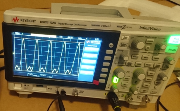
DSC_2506

Keysight DSOX1102G oscilloscope

The subject of my blog post is the DSOX1102G from Keysight Technologies (formerly Agilent), which is part of their low-end offerings that still offer very good value compared to their competitors. As with most of their oscilloscope offerings, they run an embedded operating system called Windows Embedded CE 6.0 (AKA Windows CE or WinCE), but as with most WinCE applications, you almost never see the Windows interface since it’s hidden behind a custom user interface.

Stage 1: Awakening

When the Keysight 1000-X series of digital oscilloscopes first launched in early 2017, one reviewer on Hackaday noticed that certain data-saving features on the oscilloscope would cause it to crash and reboot, noting that a mouse pointer was visible on-screen for a few seconds before the scope rebooted. That post included a GIF of him attempting to save a file which caused the oscilloscope’s software to crash, but I noticed something peculiar in one frame of the video… there was a Windows taskbar visible right before the black error screen was displayed. Interesting…!

frame_060_delay-0.1s

Freeze-frame of oscilloscope on Windows CE desktop shortly before crashing (image courtesy of Hackaday)

When I won my oscilloscope thanks to Keysight’s Scope Month giveaway program, I didn’t think much of this for a couple months until I encountered the crash screen as well. In my case, I found that the Windows CE title bar was visible on top of the oscilloscope’s crash handler; dragging the title bar simply ghosted the window on-screen and doing this a few times more caused Windows CE itself to hang. This was a pretty infrequent occurrence, so when I encountered subsequent crashes I simply let the oscilloscope’s crash handler scan the internal file systems and reboot the operating system.

However, by this point I was intrigued and wanted to find a way to learn more about what’s going on with the underlying Windows CE operating system. I found that the oscilloscope’s USB port is rather sensitive to errors and simply wiggling a USB drive in in the USB port would crash the oscilloscope. This still wasn’t enough for me to gather enough information since I could not get the oscilloscope to do this consistently.

Thus begins my quest to access the Windows CE desktop. Let’s go!

At first I tried a software-only solution, attempting to craft a .ksx firmware update file (in reality it’s just a .cab archive) that would close the oscilloscope software and open Windows Explorer – no dice. The oscilloscope software would simply throw an error message saying that it couldn’t open the update file. As it turns out, this solution wouldn’t have worked even if I could get the oscilloscope to load the update file since the oscilloscope’s software doesn’t exit to the desktop during the firmware update process anyway. Having encountered my first significant roadblock, I set my curiosity aside and simply used the oscilloscope as, well, an oscilloscope for a while.

Stage 2: Looking Deeper

True to my curious nature, one day I decided to see whether the oscilloscope would read and write to 3.5″ floppy disks (or as the young ones might call them, “3-D printed save icons” 🙂 ) using a USB floppy drive – and it did! However, I noticed one very peculiar issue: the oscilloscope would crash on boot if I left the floppy drive in the USB port when I powered it on. Eureka! – I had finally found a means to reliably crash the oscilloscope.

Unfortunately, this is where I hit my second roadblock. This crash-on-boot phenomenon would only occur if the floppy drive was the only device plugged into the USB port; it would not crash if I used a USB hub between the oscilloscope and the floppy drive. This meant that I would have to be very fast in order to switch between the floppy drive and a USB mouse/keyboard. Racing against the clock to unplug the drive and plug in my combination USB keyboard/touchpad in the middle of the boot cycle was getting tiring and frustrating very quickly. I needed a better solution… a hardware solution.

20181015_011332

Custom USB A/B switcher I built to quickly swap USB devices

Using an old USB cable, a dead USB hub and a DPDT (dual-pole, dual-throw) pushbutton switch, I created a USB A/B switcher to make the process of switching between devices fast and easy. Using this method, I was able to try interacting with the Windows CE operating system for the fraction of a second that the taskbar was visible on-screen before the crash handler barged in to ruin my fun. With the magic of my Samsung Galaxy S9’s slow-motion video feature, I was able to determine that I could send keystrokes and Windows CE would act on them accordingly – even while the system was still on the splash screen! I was able to somewhat get information about the system by blindly entering keystrokes and seeing what the output was when the oscilloscope software crashed. Enter roadblock number 2…

The ability to very briefly interact with Windows CE was great, but it was still useless since I couldn’t actually take control of it before the oscilloscope’s crash handler rebooted the system. It appeared that the crash handler had a pretty tight lock on the operating system since no amount of mashing the Windows or Ctrl+Alt+Delete would let me back into Windows CE.

Stage 3: Getting a Foothold

Once again, my random curiosity would come in handy when I decided to use my old Sony Clie PEG-NX73V (a PalmOS handheld PDA dating back to 2003) as a USB drive; it had a Data Import feature which allowed the user to drag-and-drop files onto its memory card as if it were a removable disk.

Much like the USB floppy drive, a similar crash-on-boot effect occurred when I left the PDA plugged in when powering on the oscilloscope. But… unlike the floppy drive, the oscilloscope’s crash handler seemed to interpret the PDA’s file system as a corrupt firmware partition and asked to load a firmware update file from an external USB drive.

20180830_160455

Firmware update prompt

This wasn’t very consistent behaviour, as I found that sometimes the oscilloscope software would load anyway and resulted in a very strange Windows CE window appearing with a bright-cyan mouse pointer that ghosted the screen if I attempted to move it aside. However, in this limbo-like state I was able to drag the InfiniiVision oscilloscope software’s window aside and tried mucking around the operating system that way. However, the oscilloscope software was very aggressive and would regain focus every time I clicked behind its window; after some struggling with the system’s very strange colour palette I was able to somewhat fumble my way around the operating system. I couldn’t browse the file system since I couldn’t wrestle control from the oscilloscope software long enough to do so, but I was able to bring up the System Properties dialog box which revealed that the oscilloscope is based on Windows CE 6.00 and had 100 MB of RAM at its disposal.

20180830_012949

Accessing some Windows CE dialogs while InfiniiVision software still running – what a mess!

I then decided to browse the EEVblog forums, where community members there were hard at work trying to hack extra features into the oscilloscope. From there I found out that the firmware looks for a file called “infiniiVisionStartupOverride.txt” on the USB drive’s root, and if it does this, it will try to load the oscilloscope software from there. Although it appeared that the firmware didn’t actually load the software from the USB drive, it did stop the oscilloscope software from starting up and pulling control away from me. This is where things get really interesting – the crash handler opens an Explorer dialog box, and simply entering *.* into the file name textbox would let me begin browsing the oscilloscope and USB drive’s file systems! This is exactly what I needed to being controlling Windows CE! However, I was once again presented with another roadblock: the oscilloscope would reboot after 60 seconds which limited the amount of time I could browse the operating system.


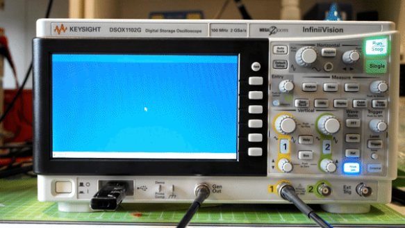
After copying a few Windows CE tools like Windows CE Task Manager, I noticed that there were two interesting processes that were still running when the crash handler was visible, “recoverInfiniiVision.exe” and “processStartupFolder.exe”; it seemed like the recoverInfiniiVision process was indeed the crash handler that was preventing me from accessing Windows CE when the oscilloscope software crashed. Killing the processStartupFolder process with iTaskMgr (Windows CE Task Manager’s trial version can’t kill processes) was enough to prevent the oscilloscope from rebooting, and killing the recoverInfiniivision process left us with a blank Windows CE desktop – I was in! Unfortunately, I was unable to restore the taskbar which made navigating the OS quite cumbersome.

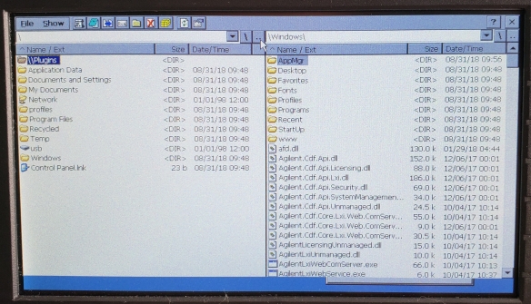
After creating a new folder on the desktop to open Explorer, I was finally able to do some real exploration (heh) of the oscilloscope’s file system. The tool Total Commander/CE was of great help since it also had a built-in text editor, which this version of Windows CE lacked.

20180830_110105

Browsing internal file system with Total Commander/CE (no taskbar just yet…)

Stage 4: Full Control

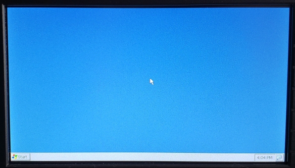
Now that I was able to see the blue sky desktop, all I needed for the full Windows CE experience was to bring back the taskbar. After a bit of Google-fu and browsing Stack Overflow, I whipped up some sample code to turn the taskbar back on. After opening this from Explorer, I had a full Windows CE desktop! YES – finally I had full control over the underlying operating system!

20180830_160618

Freedom at last – a full Windows CE desktop on my oscilloscope!

From there, I began looking through the file system to see what interesting utilities were in store. It appeared that the Command Prompt wouldn’t open at all when I tried to run it, but digging through the Registry with an editor, there was a Registry key at HKEY_LOCAL_MACHINE\Drivers\Console\OutputTo that was set to 0xFFFFFFFF. Setting that key to 0 was enough to make the Command Prompt visible on the desktop, so I created another small program to take care of this as well.

Things were looking good, so I created a batch file with all the commands required to kill the oscilloscope software, the startup folder handler, the crash handler; restore the taskbar; and re-enable the Command Prompt. However, this required I use my PDA to open the crash handler’s firmware recovery menu which prevented others from being able to reproduce this effect.

After some digging around, I found out that as soon as the splash screen appeared and the front panel LEDs began cycling, Windows CE would accept any keystrokes even without a software-crashing device present; pressing Windows and U caused the oscilloscope to hang as I was essentially opening the Start menu and selecting the Suspend option (which I guess the operating system had no means of regaining control since the oscilloscope only had a hardware power switch). With this in mind, I renamed my batch file to “a.bat” for easier typing, and tried to launch the batch file right in the boot process by pressing Windows, R (to open the Run dialog), then “\usb\a.bat” and finally Enter to run the batch file. This only caused the oscilloscope to remain at the splash screen but the Windows CE operating system was otherwise alive even if I wasn’t able to see what was actually going on. As it turns out, the crash handler is the key to making the Windows CE desktop visible, and all I had to do was add some lines in my batch file to launch and subsequently kill the crash handler. With the final touches added to my batch file, I can (semi-)automatically boot the oscilloscope right to the desktop, with just a USB drive, mouse and keyboard!

Stage 5: Yes, it runs DOOM!

Now that I had access to Windows CE, I could finally put an answer to the question “Does it run DOOM?” As a matter of fact, yes it can! It only took a year and a half after the oscilloscope’s launch, but this milestone had finally been achieved.


Stay tuned for my next blog post where I play around some more with this iconic video game – on a piece of hardware that was never intended to play games in the first place.

giphy

Doom in action at glorious 320×240, 256 colours! On an oscilloscope!

Downloads

I have released the files required for you to try this on your own scope – but be warned, I am not responsible if you brick your scope or anything else bad happens! I have only tested this on my DSOX1102G but I suspect that the rest of the 1000 X-series and other Keysight scopes that have the firmware recovery option may work too. The oscilloscope firmware is laid out such that the Windows CE file system is all in RAM and is not retained upon reboot, so any system-breaking changes to Windows will not brick the scope (the firmware files are found in hidden NAND Flash-resident directories that aren’t accessible from Explorer unless you enter them manually by name). Please leave a comment if you decide to try it yourself, and as to whether or not it works. 

You will need to format a USB drive with FAT or FAT32 and extract the .zip archive of my tool, Scope Liberator (click here!), to the drive’s root. Instructions are found in readme.txt.

If you’re interested in the source code for the support programs to re-enable the taskbar and local command prompt, I have made them available as well (they’re literally lines derived from sample code, but at least the icons for ShowTaskbar.exe and EnableLocalCmd.exe are original!).