DISCLAIMER: AC line (mains) voltage is not something to be taken lightly! Attempting to safely handle line voltages while minimizing the risk of harmful or fatal electric shock is the main motivator for me to design and build this circuit. However, I am no electronics engineer and I definitely have no formal training on international standards pertaining to high-voltage safety. I accept no responsibility, direct or indirect, for any damages that may occur if you attempt to make this circuit yourself, including personal harm or property damage. Additionally, there is no warranty or guarantee, express or implied, on any content pertaining to this blog post (or any other posts).
UPDATE (November 19, 2018): Added isolation voltage ratings for the amplifier and DC-DC converter.
As seen on Hackaday!
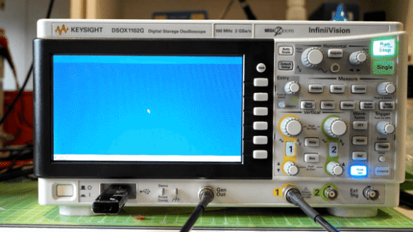
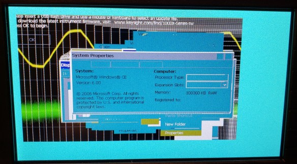
Back in mid-2017 I won a Keysight DSOX1102G digital storage oscilloscope (DSO), a piece of equipment long on my wish list but never acquired until then. One thing I’ve wanted to be able to measure with an oscilloscope for a long time was the waveform of the AC utility (in other words, the wall outlet). However, doing so presents a very real risk of blowing equipment up or shocking yourself (and possibly other people). In order to prevent this, I needed a way to perform measurements on the AC line without being directly connected to it; in other words, I need galvanic isolation.
Isolation Methods
There are many different ways to achieve galvanic isolation. Common methods are the use of transformers and optocouplers, but they each have their own disadvantages.
Optocouplers (aka optoisolators) are a common component used for isolation, but they require a fair bit of external circuitry to work correctly – not to mention its current transfer ratio (CTR) varies with temperature and age, resulting in drifting measurements over time if a feedback circuit isn’t used. They also aren’t very fast; the common Sharp PC123 optocoupler has a cutoff frequency of only 80 kHz and a response time of 3-18 µs (but newer ones can be much faster).
Transformers don’t require active circuitry and would make stepping down voltages simple. However, their inductive nature causes issues when measuring waveforms with low-frequency content and sharp edges (like the output from modified sine wave inverters), resulting in inaccurate measurements due to the ringing and other distortion that the transformer creates. Additionally, common iron-core transformers aren’t very good at capturing frequencies above 20 kHz.
Solution: Isolation Amplifiers!
I settled on using an isolation amplifier to provide the necessary protection from the AC line and the oscilloscope. Several years ago TI provided sample kits for electronic motor drives, with one component being the AMC1200 isolation amplifier; this is the IC that I used in my AC waveform viewer – however, note that there are some limitations that I will address later in this blog post.
The AMC1200 uses TI’s digital capacitive isolator technology, using high-voltage SiO2 (silicon dioxide) dielectric capacitors on the chip itself for high voltage protection. The amplifier’s input is essentially digitized using a sigma-delta modulator, whose output is then sent digitally across the isolation barrier before being demodulated back into an analog output. It is rated for a working isolation voltage of 1200 Vpeak (848 Vrms), and a maximum isolation voltage of 4000 Vpeak (2828 Vrms), well above the typical voltages experienced on a 120V line.
AC Waveform Viewer Construction
-

- Top side of AC waveform viewer. Note the isolation holes drilled out that separate the low and high voltage sides.
-

- Underside of AC waveform viewer. Note how column N is all drilled out for isolation, and the voltage divider on column X is fully encapsulated in epoxy.
As with most of my projects, my AC waveform viewer is built on FR4 fiberglass perfboard. The isolation components used are the AMC1200 isolation amplifier by Texas Instruments, and its corresponding power supply is the NXE1S0505MC isolated DC-DC module by Murata. It is rated for reinforced insulation up to 125 Vrms and basic insulation up to 250 Vrms, with a production-tested Hi-Pot rating of 3 kVDC. It does provide reinforced insulation at the voltages used in North America, but is still the weaker link in terms of maximum isolation voltage.
The AMC1200 features differential inputs and outputs, with a maximum input voltage of +/- 200 mV intended for use with low-resistance current shunt resistors.
One potential problem with perfboard is that the through-holes compromise the high-voltage isolation of the circuit (reducing the creepage and clearance distances), acting as multiple series spark gaps. The solution to this is similar to how isolation slots are used on commercial PCBs; that is, drill out the holes! This greatly increases the distance between each side of the circuit and improves the safety of the circuit.
The AC voltage input is scaled down to a manageable level via a resistive voltage divider. I used four high-precision 300kOhm resistors in series, plus a 1kOhm resistor placed across the AMC1200’s input terminals. Since the input is floating thanks to galvanic isolation, I decided to place the amplifier’s input in the middle of the voltage divider (that is, 600kOhm of resistance is present from the neutral and line terminals) to provide some extra protection from harmful electric shock; 120 Vrms / 600 kOhm = 0.2 mA to ground is the maximum amount of current that could possibly flow if I were to contact this floating node on the amplifier (this calculation assumes that my body has zero resistance, but human skin resistance is generally much higher than this). The voltage divider and the AC input terminals of my waveform viewer are further insulated with a layer of clear epoxy for even more protection.
The power supply terminals are fused with a 500 mA fuse before being protected by an SMAJ5.0A TVS (transient voltage suppression) diode and filtered with a 22 uF tantalum capacitor. The AMC1200’s output terminals are protected with 5.1 V Zener diodes at the terminal blocks for ESD and overvoltage protection.
Due to the floating nature of the waveform viewer, this essentially is a differential probe for my oscilloscope (and most high-voltage differential probes actually aren’t isolated!).
Circuit Limitations
No circuit is perfect, and mine is no exception. Here’s a few issues with my circuit that I’d like to address:
Isolation limitations
The AMC1200 only provides “basic insulation“; that is, it will provide protection from electric shock as long as its insulation barrier is not damaged (in other words, there is no redundancy). Circuits that have terminals that can be directly touched by humans needs “reinforced” or “double” insulation to be compliant with international regulations.
The NXE11S0505MC isolated DC-DC converter has a maximum working voltage of 125 Vrms for reinforced insulation and 250 Vrms for basic insulation, with a Hi-Pot test at 3 kVDC. This is lower than the AMC1200’s maximum voltage of 4000 volts, but these should still have enough headroom to keep me safe in the event of a mild voltage spike. It might prove useful to add some sort of surge suppression with a MOV (metal oxide varistor) or similar device.
The perfboard layout is also sub-optimal for the sake of isolation. Despite drilling out a row of holes to increase the creepage and clearance distances, it isn’t quite enough to meet regulations, as the clearance is only 3 mm and the the creepage isn’t much better, around 4 mm. This is still more than enough to withstand normal AC line voltages, but there is always a chance that higher-voltage transients will make their way onto the line and the isolation barrier needs to take this into account.
Output limitations
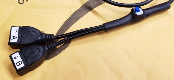
The AMC1200 provides a differential output that is centred (common-mode voltage) at 2.5 V, which can be an issue with single-ended inputs like that on an oscilloscope. I’ve worked around this by using a floating power supply, like a USB power bank, and connecting the oscilloscope’s ground terminal to the AMC1200’s Vout- pin. Also, the AMC1200 has a limited bandwidth of 60-100 kHz, but for the purposes of waveform monitoring it is sufficient; however, the amplifier’s noise and offset also negatively impacts performance as the high attenuation ratio essentially amplifies these values to the point where the AC waveform looks like a 2 Vdc offset and the noise level is so high that I need to use the averaging or high-resolution acquisition modes on an oscilloscope to get a clean waveform.
Power supply limitations
The NXE1 isn’t quite suited for such a low-power task as operating a single amplifier input. According to the datasheet, the output voltage can rise to twice the rated voltage if it is loaded with less than 20 mA. To combat this, I placed a 5.1 volt Zener diode across the output to provide regulation, which unnecessarily wastes power. Another regulated module like the NXF1 series would be a better choice, and the unit cost at one-off quantities isn’t a huge deal either.
Room for improvement
With this circuit working properly, I had plenty of ideas to make the second iteration even better:
Simultaneous voltage/current inputs
With the ability to measure current, I can perform measurements on the current draw of a device, allowing me to determine the power factor of a device.
True single-ended outputs
Most ground-referenced devices like oscilloscopes are not meant to handle differential inputs directly. Multimeters, especially battery-powered ones, are an exception.
Reinforced insulation rating on amplifier
The AMC1200 is only rated for basic insulation, so having an amplifier rated for reinforced insulation would provide greater electric shock protection. Alternatives like the Silicon Labs Si8920 could be a viable solution.
Waveform captures
-

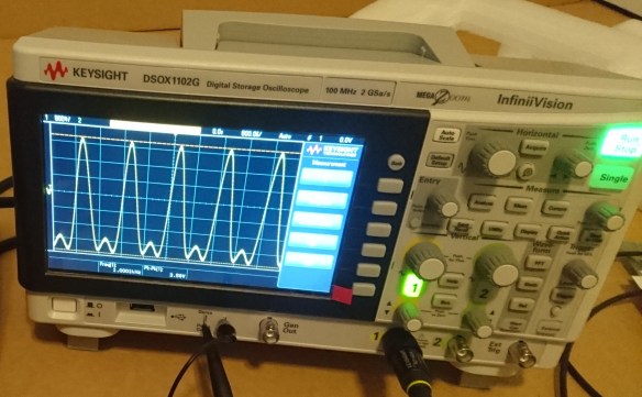
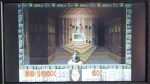
- Calgary’s AC line waveform (captured in Normal mode, mind the noise!)
-

- After enabling High Resolution mode, much less noise!
-

- AC waveform viewer accurately reading modified sine wave inverter
-

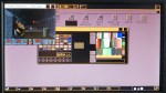
- Real-world voltage sag captured, thanks to the DSO-X Mask analysis feature!
Conclusion
Despite its ubiquity, AC power is a force that must not be taken lightly. Performing measurements on it, especially when viewing its waveform on a non-isolated oscilloscope, requires extreme caution as line voltage (especially in countries where 230 V is common) can easily injure or kill.
Using a voltage divider and isolation amplifier allows for safer measurements of the AC line without introducing distortion, especially compared to transformer-based implementations; this is critical when measuring the waveforms of modified sine wave inverters.
My implementation of an isolated differential probe helps protect me from electric shock when making measurements, while costing much less than a commercial high-voltage differential probe (for example, the CT2593-1, costs almost $330 USD on DigiKey).
But… which one would you trust more?