I ordered some sample chips from TI a few weeks ago, most of them being lithium-ion battery “fuel gauge” chips. These chips are used in electronic devices to determine exactly how much energy is in the battery, and if the chip’s sophisticated enough, provide a “time until empty” prediction.
The bq27421 from TI is packaged in a tiny 9-ball grid array, packaged as a wafer-level chip scale package (WLCSP). This means there is no epoxy covering like normal ICs, making for a compact design that’s a good thing for space-constrained applications like modern cell phones. I’ll talk about this chip later on in this post.
The tiny BGA package means that prototyping with these chips is difficult if not impossible, depending on how large the chip is that you’re working with. The bq27421 is about 1.6 mm x 1.6 mm, which is less than 1/3 of the size of a grain of rice. No way you’d be able to put that on a breadboard… right?
 Well, you can, with a small breakout board, some magnet wire, epoxy (a bigger deal than you might initially think), patience and steady hands. I mounted the chips in what I call a mix between dead-bug (where the contacts face up as if the chip was like a dead bug on the ground) and chip-on-board construction (where the chip is glued directly to a board, wire-bonded and then covered in epoxy). I used some SOIC-to-DIP boards from DipMicro Electronics (link). I often use these boards when doing work on prototyping board since using these surface-mount parts reduce the board’s height compared to using actual DIP packaged chips (which are much less common for modern ICs anyway).
The chip is first affixed to the breakout board using a small amount of epoxy and allowed to cure for several hours. The epoxy, from what I’ve found, is crucial to your success; superglue and other adhesives won’t stand up to the heat of a soldering iron, and if it loosens you can end up ruining your chip and wasting your time spent working on it.
After letting the epoxy cure, I then prepare the bond pads around the chip. I place a liberal amount of solder on each pad to allow easy connection with the iron later; I want to minimize the stress on the tiny 40-gauge magnet wire because once the connection is made, the solder ball that the chip came with won’t be as easy to solder to the second time around.
-

- Chip partially soldered
-

- Pinout I created for the board
-
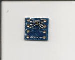
- Scan of the chip before covering with epoxy
Next up is the actual soldering process. I created a pinout for the board in PowerPoint to help plan out how I’ll solder the wires. After tinning a long length of 40-gauge magnet wire, I then solder the wire first to the solder ball on the chip, then solder the other end to the pad I previously put solder on. To minimize the stress on the wire afterwards, I use a small utility knife to cut the end of the wire where the pad is. I then complete this for the rest of the contacts. This took me an hour and a half the first try, but took me about 20 minutes the second time around. Also, for my second try, for the BAT and SRX pins, which carry the full current for any loads connected, I used 30-gauge wire-wrapping wire to allow a bit more current-carrying capacity. It probably is overkill since the maximum current rating for the bq27421 is 2 amps continuous, but I felt a bit more at ease connecting the pins this way.
After checking for short and open circuits with a multimeter I then placed headers onto the board and put it into my “evaluation board” that I created just for this chip. Using an EV2400 box from TI, used to connect to their vast range of battery-management chips, I connect the box to my PC and run their GaugeStudio software to verify that the chip works.
-

- Test board
-

- EV2400 interface
-

- GaugeStudio
… and it does, like a charm! I was able to communicate with the chip and also view its operation in real-time.
One thing that was causing me trouble before was that after removing the battery and putting another one in, I found that the gauge chip sometimes wouldn’t be recognized by the PC. Being unsure why it was doing this, I dug through the reference manual, and found one tiny part in the manual that showed me why it wasn’t working consistently.
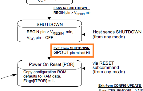 The GPOUT pin was left floating on my board, and the chip requires a logic high signal before it starts up. This brings back memories of my digital electronics class in college; these floating inputs can cause all sorts of trouble if you’re not careful, and in this case, it was mentioned only once in the reference manual. After using a 1 megohm resistor to pull up the pin, the chip worked flawlessly. Now that I verified that the chip was working, I mixed up some more epoxy and covered the chip, making sure that the bond wires and chip were covered to prevent damage.
After all that, I had a couple working highly-advanced battery gauges that I could fool around with, and also learned a couple things about deadbugging SMT components and also the basics of chip-on-board construction.
