KitchenAid induction cooktop service manual

In preparation for a future post in which I do some failure analysis on my KitchenAid KICU509XBL induction cooktop, I dug up the service manual I had laying in one of my document drawers and have scanned it into a PDF. Download the PDF file here.

Since Googling for the cooktop’s error/failure codes didn’t turn up anything useful, I’ll post them here so that people can find it more easily (note that I’ve paraphrased it from what’s listed in the PDF itself):

Failure types:

  1. Power control board: Affects only one burner, with the rest remaining functional.
  2. Usually from the power control board, but could be some exceptions: Affects all burners associated with that control board, but any burners that aren’t using said board will still work.
  3. User interface board: Entire cooktop will be unusable.

Error codes:

  • F12: Type 1 – Insufficient current to a burner’s electromagnetic coil.
  • F21: Type 2 – Mains power supply frequency is out of range.
  • F25: Type 2 – Cooling fan is stuck or dead. The specific fan that has failed can be determined by which side the F25 error code is appearing on the user interface board.
  • F36, F37: Type 1 – A burner’s temperature sensor has failed.
  • F40: Type 1 or Type 2 – Power control board has failed.
  • F42: Type 2 – Mains power supply voltage has a problem, perhaps an open fuse on the EMI filter/mains input board.
  • F47: Type 2 – User interface board cannot communicate with the power control board, and/or its fuse is blown. (This failure code is what appeared on my particular cooktop.)
  • F56: Type 3 – The configuration data on the cooktop’s user interface board EEPROM is invalid.
  • F58: Type 2 – The configuration data on the cooktop’s power control board EEPROM is invalid.
  • F60: Type 3 – User interface board has failed.
  • F61: Type 2 – Power control board has failed, likely because it is not receiving enough voltage.
  • C81, C82: Type 2 – Cooktop is overheating.

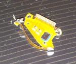
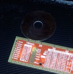
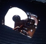
EDIT (November 6, 2015): The F47 code, in my case, was because the power control board (which is responsible for driving the induction coils to heat up the cookware) had short-circuited somehow. Either way, it burnt out all of the transistors and the diode bridge, which then caused its fuse to blow, and at one point it tripped the main breaker in the house.

I suspect it was caused by using the largest element (the rear right burner) on the Boost/P setting, which overloaded the electronics and caused them to fail dramatically. After getting the board replaced (twice), KitchenAid said they do know about this issue to some extent, and repaired our cooktop free-of-charge despite being out of warranty for several months.

Advertisement

How NOT to cut monocrystalline solar cells

The notion of “free electricity” has had some allure for me for quite some time. Back in the middle of high school, with a relatively full pocket after a hard summer job operating rides at a local outdoor theme park, I thought “Hm… Calgary sure gets a lot of sun. Now what if I tried to harness its energy?”

Back in late 2011 I purchased a set of 44 6″ by 6″ monocrystalline solar cells (the good stuff) off eBay. These cells sat unused for years until I tried to build a small panel with one of the cells. I wanted to have a small portable panel that I could bring around to charge my phone (I shoehorned a Nokia BL-5C into my Samsung Galaxy S II and it still works better than my fake “Samsung” battery I bought off eBay for $7 or so).

Cell plan created in Publisher

Cell plan created in Publisher

I created a layout of the way to cut up the cells using Microsoft Publisher, as it has the ability to create shapes in a what-you-see-is-what-you-get manner. I divided the 6-by-6 inch cell into 12 subcells. One whole cell is rated for 4 watts in full sun (0.5 volts * 8 amps), so each subcell should produce ~667 mA or 333 mW. However, the corner cells will have 1.5 cm^2 less area because monocrystalline cells are manufactured from a round wafer, but the output difference isn’t of huge concern to me. Of course, the useful power output of the cells will be much lower than this, but designing for that’s all part of the fun (or pain, depending on how you look at things).

I used a diamond cutting disk designed for a Dremel or other rotary tool, and scored the top side of the solar cell. If things went as planned, I could “snap” the cell at that scored line and it should break cleanly.

Since at this point the cell was basically ruined (Most of the fragments are usuable, provided the silver conductive pad is present on the back of the cell), I decided to cut up some “usable” sections by scoring both sides (and with more depth). It worked… okay I guess. The yield was poor but I did have a few cells that split acceptably.

Overall, the panel’s usable area is much less than what I expected. With 12 subcells I can expect about 1-2.5 watts from this panel. Oh well, live and learn.

Next up is to acquire a proper glass-cutter with a flat working surface…

The Operation Failed Successfully: New series on this blog

I’ve created a new category for my posts, named “The Operation Failed Successfully” in a somewhat mocking term of the Windows error “The operation completed successfully.” It’s intended to be used in a similar manner as Hack A Day’s “Fail of the Week”, showcasing some… less successful ideas of mine.

(Part 2 of 2) Microdrive Adventures: Looking into (and butchering) the Hitachi Microdrive and Seagate ST1 CompactFlash hard drives

(Part 1 viewable here)

Content advisory: electronics gore! 😀

refundI sent screenshots from Hard Disk Sentinel to the seller of the microdrives, and they refunded my money but didn’t want the drives back. Even then, it’d probably be a good idea to destroy the drives since re-use of them would be a bit… fraudulent after getting refunded. I decided to throw the drives around to see how well they’d hold up to physical abuse.

The Microdrive died when I whipped it against the concrete floor of my basement, go figure. The impact was strong enough to bend the steel frame but not enough to shatter the glass hard disk inside. Obviously, the disk didn’t spin up or enumerate in Hard Disk Sentinel. Now that the drive’s murder has been accomplished, it’s autopsy time!

The Seagate ST1 was put through a similar treatment, but it died much less gracefully when plugged in. The main controller chip (I think) shorted internally, and after about 15 seconds of being powered up, it released the magic smoke. The board’s plastic liner was melted where the chip shorted out. The drive internals weren’t much different than the Hitachi drives so I didn’t bother taking pictures of the drive’s insides.

After the damage was done, the drives were promptly put in a small plastic bag to be put in an electronics recycle bin.