UPDATE (July 19, 2020): I’ve analyzed a 128GB version of the High Endurance card, and it appears that SanDisk is using 3D TLC Flash.
Dashcams: they can be a crucial tool when reconstructing events in a vehicular incident, or a source of entertainment when watching compilations on YouTube. Like any modern device, they generally use SD or microSD cards as their storage medium. However, not all cards are created equal.
Cheaper cards, like SanDisk’s Ultra lineup, use cheaper TLC (triple-level cell) NAND Flash that is ill-suited to the harsh working conditions of a dashcam. Not only does the card have to endure temperature extremes, the constant writes can burn through the Flash’s write cycles in short order. In fact, SanDisk specifically denounces this line of cards for use in continuous-recording applications.
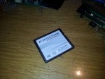
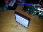
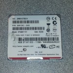
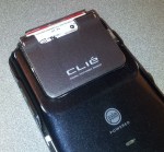
The solution: high-endurance memory cards! These cards (at least in theory) use more durable MLC or even SLC NAND Flash, which can take many more write cycles. I purchased the 64-gigabyte model, the SDSQQNR-064G-G46A.
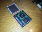
Unboxing
The card’s packaging isn’t much different than SanDisk’s typical microSD card offerings. The paper-and-plastic package includes a small blister pack that holds the microSD card itself and the full-size SD card adapter, without a carrying case (granted, the memory card is expected to stay inside the dashcam for most of its working life).
The packaging also includes a license key for a 1-year subscription to the RescuePRO data recovery software (although in all honesty, you’d be better off using the free PhotoRec software instead).


Endurance Rating
SanDisk’s lineup of high-endurance memory cards are designed for use in very write-intensive workloads, such as constant video recording.
Unfortunately, the endurance specifications for these cards are (probably intentionally) vague, only providing a set number of hours of video recording. However, we can infer a rating with a little bit of math.
SanDisk’s card packaging defines Full HD video to be 26 Mbps, which is equivalent to 3.25 (binary) megabytes per second. This equates to 11,700 megabytes per hour, or 11.426 gigabytes per hour. With a rating of 5,000 hours at this data rate, we get a specified endurance of 57,128.91 gigabytes written, or 55.79 terabytes written (TBW).
Memory cards, like other block-based storage media, often define capacities with decimal prefixes, whereas computers usually binary. A “64-gigabyte” card is really 59.605 binary gigabytes (“gibibytes“) in capacity, but in this blog post I’m using the Windows notation of gigabytes; that is, calculating in binary but displaying as decimal. 😛
Therefore, we get a final calculated P/E (program-erase) cycle count of… 936 cycles. This is more in line with traditional 2D TLC NAND Flash, so I suspect that this rating is either based on different bitrates, or SanDisk is being really, really conservative in their estimates – or heck, maybe this really is just TLC NAND Flash that’s being configured and/or warrantied differently by SanDisk. As much as I am tempted to remove the epoxy coating that covers the manufacturing test pads in order to get a NAND Flash signature directly, I like having a warranty for at least a few years. Maybe I’ll buy another card to try this on…
UPDATE (July 19, 2020): I got my paws on another card (the 128GB variant), and did some reverse-engineering work on it to determine what Flash SanDisk used. It turns out they used 3D TLC NAND, which is still quite durable and reliable due to the use of larger process geometries. The Flash should easily withstand thousands of write cycles without much issue.
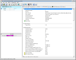
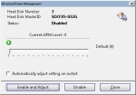
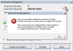
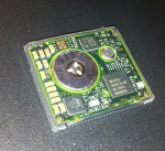
Card Information
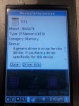
Using an older laptop with a true SD-compliant slot (most newer ones are just USB card readers internally), I was able to grab the card’s metadata from Linux. These information files are found in /sys/block/mmcblkX/device, where X is usually 0 depending on your host machine. Android used to be able to do this as well, but nowadays it’s not possible without a rooted operating system.
| Item | Value |
|---|---|
| CID (Card ID) | 035744534836344780ed1bbb9e013100 |
| CSD (Card Specific Data) | 400e0032db790001dbd37f800a404000 |
| Manufacturer ID | 0x03 (SanDisk) |
| Manufacture Date | January 2019 |
| Device Name | SH64G |
| Firmware Version | 0x0 |
| Hardware Revision | 0x8 |
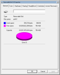
Initial Formatting
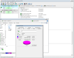
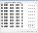
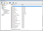
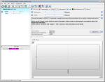
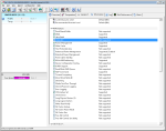
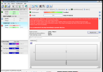
The card is formatted as exFAT, with a 16 MB offset (that is, the first 16 MB of the card is unallocated), with an allocation unit size of 128 kilobytes. It uses a very basic MBR (Master Boot Record) partition structure, with the first sector being the bare minimum to be recognized as a valid structure.
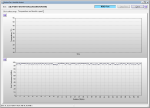
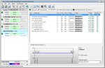
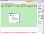
-
- The card’s file system properties in Windows.
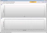
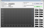
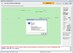
-

- The card’s partition structure in Hard Disk Sentinel.
-
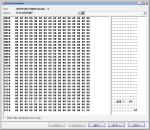
- The card’s MBR.
Performance
Now that I’ve probably irked some of my readers with my usage of decimal and binary prefixes, it’s time to see how fast this card can go. SanDisk’s own ratings for the card are very brief, citing a sequential read/write speed of 100 and 40 MB/s respectively. It is rated for the V30 Video speed classification, which guarantees a minimum of 30 MB/s sequential writes continuously.
All the tests below were performed on my desktop computer using a FCR-HS4 USB 3.0 reader from Kingston, which is based on the Realtek RTS5321 chipset.
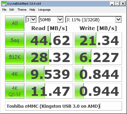
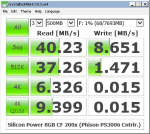
CrystalDiskMark
CrystalDiskMark is the de-facto standard for storage benchmarks. I’m using the 64-bit edition of CDM, version 5.2.0.
| I/O Type | Read | Write |
|---|---|---|
| Sequential QD32 | 91.80 MB/s | 60.56 MB/s |
| Sequential | 93.33 MB/s | 61.66 MB/s |
| 4K Random QD32 | 8.319 MB/s 2129.7 IOPS |
4.004 MB/s 1025.0 IOPS |
| 4K Random | 8.121 MB/s 2079.0 IOPS |
3.971 MB/s 1016.6 IOPS |
The sequential I/O speeds are on par with a modern microSDXC card, and the IOPS aren’t too shabby either; they exceed the IOPS requirements for the A1 performance class which requires R/W IOPS of 1500 and 500 respectively. This could make this type of card a viable option for other write-heavy environments – this includes single-board computers (SBCs) like the Raspberry Pi, where memory card failures due to excessive writes are common.
ATTO Disk Benchmark

The card’s read/write performance levels off at around the 64-kilobyte mark during testing, showing that operations smaller than this incur a significant performance penalty. This may also be indicative of the internal page and block sizes of the NAND Flash itself.
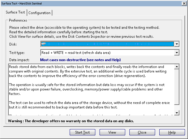
Hard Disk Sentinel
Hard Disk Sentinel comes with a bunch of disk benchmarking tools, including some to test the entire “surface” of a drive. I used the software’s Surface Test tool to measure the card’s performance before and after filling the drive with data – first with random data, then with all zeroes.
Random Seek Test
The Random Seek Test measures the card’s latency when performing random “seeks”, although more accurately it reads a single sector from a random location.
| State | Average Latency | Minimum Latency | Maximum Latency |
|---|---|---|---|
| Empty/Initial (0x00) | 360 µs | 350 µs | 420 µs |
| Random Fill | 600 µs | 590 µs | 670 µs |
| Zero Fill | 600 µs | 590 µs | 690 µs |
The card initially had about 420 microseconds of latency, but after filling the card with random data, this increased to 670 microseconds. Filling the card with all zeroes again did not improve performance, and his isn’t helped by the fact that SD cards generally lack the ability to “TRIM” unused sectors like SSDs or eMMC chips.
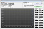
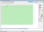
Full Surface Read (or at least an attempt)
-
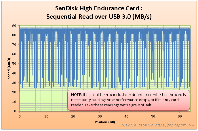
- Sequential read speeds over the length of the card, taken from Hard Disk Sentinel.
This is where things get a bit… interesting. It was around this time that I noticed some performance inconsistencies that didn’t show up on other benchmarks. Although the I/O speeds largely matched what my other benchmarks revealed, I noticed frequent dips below normal, often down to the mid-20 MB/s range! I wasn’t sure that this was necessarily the card’s fault (pauses in read/writes could result in performance degradation on a device if it can’t buffer the writes well enough), or if my card reader/operating system/etc. was responsible.
I decided to hold off on publishing the sequential write test until I get this issue figured out – perhaps it’s worthy of a blog post all on its own…