eMMC Adventures, Episode 4: Recovering data from physically damaged BGA eMMC Flash storage chips

As seen on Hackaday!

The ball grid array (BGA) chip package has been instrumental in getting modern electronics to fit in smaller and smaller spaces, as it uses tiny balls of solder on the bottom of the package to make electrical connections, instead of copper leads on the edge of the chip package. This allows for hundreds of connections to be made in a small amount of PCB area, but their size also makes them very vulnerable to damage as well.

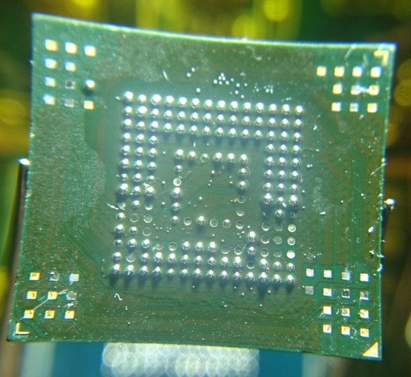
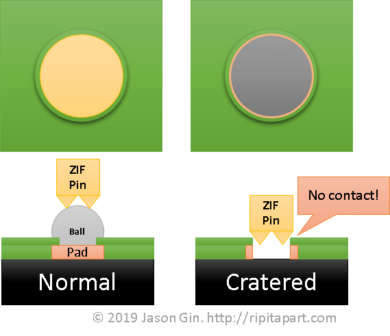
One common way for BGA chips to become damaged is called “pad cratering“, where the copper pad on the package’s substrate (basically a wafer-thin circuit board) separates and leaves behind a crater.

In the case of eMMC (Embedded MultiMediaCard), its package type is known as an FBGA (Fine-pitch Ball Grid Array), so the area of each pad is very small (0.4 mm in diameter!); it doesn’t take much at all to crater the pad – even gently removing solder with solder wick and generous amounts of flux can still cause damage! Most of the pads on an eMMC package are unused, but if any one of the DAT0, CLK, or CMD pads are damaged, then the chip is rendered unusable, even if the chip is placed into a socket for data recovery. If the DAT1-DAT7 pads are damaged, data recovery becomes much slower as the chip is forced to use fewer lines to transmit data (the MMC standard supports data over 1, 4, or 8 lines).

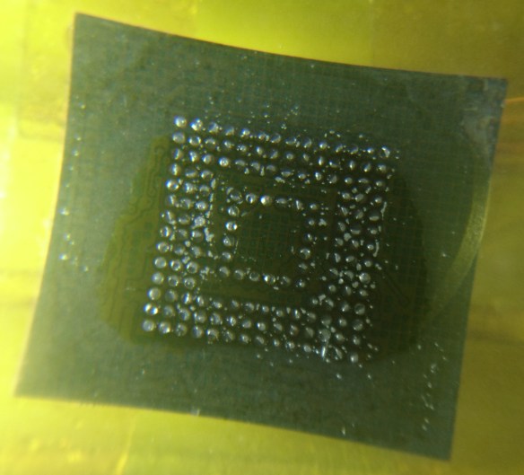
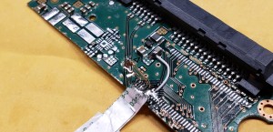
However, there is some hope. Many FBGA packages, including eMMC, use pads that are SMD (solder-mask defined); this means the solder mask is what defines the size of the pad, not the copper itself. Therefore, when the pad gets cratered, often there is a “halo” of copper left behind that still has a chance of getting an electrical connection.

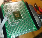
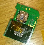
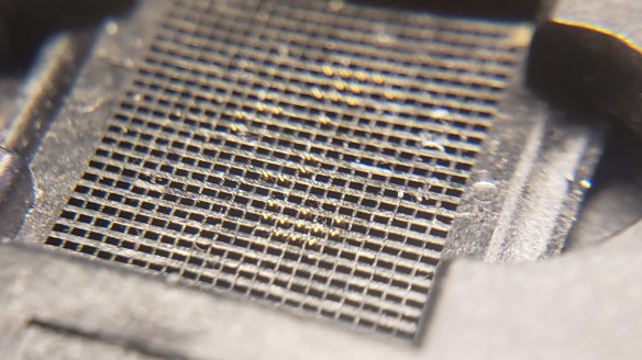
The trick is how to to get a flat conductive area that a chip socket can use to get a reliable connection (without a copper pad, soldering is no longer an option). The eMMC socket adapter I used breaks out the eMMC onto an MMCplus-shaped PCB that can be inserted into any commercial SD card reader.

Filling in the Blanks

There are a few possible materials that can be used to restore contact area on a damaged BGA pad. One possible option is a silver-filled conductive epoxy, but I have not tested its efficacy; an additional consideration is that the volume of the filled-in crater might not be enough to get a filling with sufficiently low resistance for a good connection.

Another option is using solder paste, which I used in this case. Unfortunately, solder’s surface tension is our enemy when trying to fill in a flat area (it wants to form cohesive balls and therefore won’t want to stick to the ring of copper left around the crater), so a means of forcing the solder into the crater requires something flat, rigid and capable of handling the high temperatures experienced during soldering.

At first I tried Kapton (polyimide) tape, but that was a massive failure since it didn’t have the rigidity to stay flat when the solder paste began to melt, and the liquid flux rendered the adhesive useless.

The solution to the issue came in the form of glass. Specifically, I used very thin (0.15 mm thick!) glass “cover slips” normally used to prepare specimens for viewing under a microscope. These can be very inexpensive and one can obtain hundreds of them for a few dollars. The key is to fill the craters with the solder paste by using a knife as a squeegee, then placing the cover slip on top of the eMMC and reflowing it.

It took a few iterations for the pads on some of my eMMC chips to be restored sufficiently, as the volume taken up by the solder will be less than the paste and its accompanying flux. It doesn’t have to fill the entire crater – it just needs to be enough for the eMMC socket’s pins to make a solid connection.

Conclusion

The high-density nature of modern BGA chips is both a blessing and a curse. When trying to do data recovery from devices that use such tiny chips, such as eMMC or UFS Flash storage, sometimes the desoldering process is too much for the chip’s pads to handle. With some ingenuity (and thin glass), it might be possible to temporarily restore enough conductive pad area to get the data off with the help of an eMMC socket.

eMMC Adventures, Episode 3: Building a custom adapter to use cheap eMMC-based 32GB SSD modules

As seen on Hackaday!

While on my quest for more eMMC-based storage devices, I stumbled upon a few devices that piqued my interest: eMMC-based SATA SSDs! I found two models of particular interest: Dell had M.2 modules with a 2.5″ adapter, and HP had custom boards intended for use in cheap laptops (for example, the HP 14-an012nr). Although the former was easier for me to use (but not acquire), I will be focusing on the latter in this blog post.

Overview of HP 14-am/14-an Series SSD Module

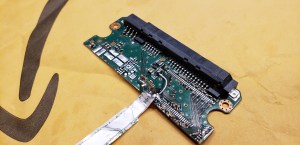
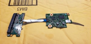
Unlike Dell’s convenient M.2 modules, the cheaper boards from HP (costing about $12 USD when I purchased them) had a physical interface intended for use only with its intended host; despite using a SATA interface, physically it used a 10-pin FFC (Flat Flexible Connector, aka “ribbon cable”) since it was designed to work only with HP’s 14-am/14-an series of  low-cost laptops. The boards are labeled “DINERAMD-6050A2862201-DB-A01” and have a copyright date of 2016 in my case.

The BayHub OZ788WR2 Bridge Chip

These eMMC-based SSDs use a curious little chip, the BayHub OZ788WR2 (labeled 788WR2A on the chip itself). It is an SD/MMC-to-SATA adapter, with an SD UHS-II/MMCplus HS200 device interface and SATA II 3Gbps host interface. Apart from the brief description from the manufacturer, no other data is available for the chip (and even finding the chip online is basically impossible).

It’s a shame that so little is known about this chip (and that it’s so rare to find in actual devices), especially since high-performance SD-to-SATA adapters otherwise do not exist, as they use outdated SD-to-CompactFlash adapter chips that are limited to 25 MB/s speeds. If I had the engineering expertise, time, money, and ability to acquire these chips, I’d totally try to make an SD-to-SATA adapter with this chip… but alas, that will still remain a fantasy.

Step 1: Pinout Discovery

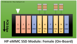
The single connector on the eMMC SSD is a ZIF FFC (Zero Insertion Force, Flat Flexible Connector), with no publicly available pinout or any other information. Perhaps this was why I got them for so cheap – apart from holding only 32 GB, nobody could even use them in their own computer even if they wanted to!

When trying to reverse engineer an unknown connector pinout, one needs to first look for ground pins. This is easily accomplished by using a multimeter with a continuity or diode test function, with the multimeter’s positive lead on a known ground point on the DUT (Device Under Test) – screw holes are often good candidates to look for. Ground pins will read as a short, but active IC and power pins will look like a forward-biased diode – appropriately 0.5 to 1 volt. I found 3 power pins (these are often grouped together on connectors for greater current capacity), 3 ground pins, and 4 SATA data pins. The data pins don’t show up on the multimeter test since they have series AC coupling capacitors, but they are easily located next to the connector and have clearly visible differential pairs leading to them.

The issue now is trying to find what order the SATA data pins are in, and how they relate to a regular SATA interface. As it turns out, the pinout is very simple: it matches the pinout of the 7-pin regular SATA interface! This makes sense as the SSD module and the laptop itself are designed to be cheap to manufacture.

Step 2: Building the Adapter (Take 1)

With the pinout known, the harder part is wiring up the connector. However, without a matching connector for the ribbon cable, I have no choice but to solder to it.

As I soon learned, not all flex cables are made of heat-resistant polyimide (aka Kapton) – this one melted before I could even tin the exposed leads. No matter, I’ll just use my trusty magnet wire and hook up the data and power lines! With the help of a salvaged SATA connector from a dead laptop drive, I was able to cobble together a crude adapter for the eMMC SSD board.

Although I didn’t end up taking a picture of the adapter, it wasn’t pretty. It also wasn’t very functional either – although the eMMC SSD board was able to identify itself (on my PC it showed up as a “BHT WR202HH032G E70211F5”), I couldn’t actually perform any data transfer without causing the OZ788WR2 to log hundreds of interface checksum failures (but hey, it supports S.M.A.R.T. data reporting!).

After some tweaking of the wire spacing, I was able to get the adapter stable enough to work, and encased it in hot glue for protection. It lasted a few weeks but eventually stopped working because one of the data wires broke off inside the blob of hot glue. Additionally, the outer contacts on the ribbon cable connector were peeling away from its plastic substrate. It was time for a rebuild.

Step 3: Building a Dedicated eMMC SSD (the teaser!)

Since I had multiple eMMC SSD boards, I took one, replaced the eMMC with a 128GB one from Samsung (the KLMDG8JENB-B041) and removed the ribbon cable connector. In its place, I used some very thin twinaxial cable from a dead MacBook and used a gutted CFast-to-SATA adapter for a shell. Stay tuned for that in another blog post!

Step 4: Building the Adapter (again!)

Much like my previous attempt, I used a salvaged PCB from a dead laptop drive, but left a lot of it instead of chopping it off directly at the connector. This particular one was a dead Samsung HDD, and it had one particular feature that I could use to make a stronger adapter: it had a TSOP footprint for the DRAM cache, which was just the right pitch for me to solder the ribbon cable to!

With a little help of my hot air rework station, I removed the DRAM cache and DC-DC converter, leaving the SATA AC coupling capacitors and the power input components (filtering choke and capacitors, and input overvoltage protection) behind.

After scraping off some solder mask, I soldered the SATA data wires and the ground wires surrounding them with very thin magnet wire, trying to keep the data pairs as close to each other as possible to minimize the chance of interference causing problems. The power wire was soldered to the power input components, right next to the input capacitor for better power delivery.

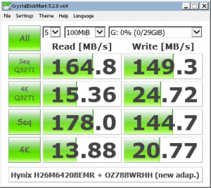
After checking with the multimeter that no short circuits were present, I hooked up an eMMC board and plugged it into my PC. It enumerated without issues, and running several tests including CrystalDiskMark, h2testw, and Hard Disk Sentinel’s random read test, amassing several hundreds of gigabytes in reads and writes with zero CRC errors logged in the S.M.A.R.T. data.

With everything checked out, I cleaned the circuit with isopropyl alcohol and covered the exposed end of the ribbon cable and the magnet wires with clear epoxy for protection. I also used a bit of epoxy on the flex connector to re-secure the lifted contacts to the substrate.

Conclusion

With a bit of wire and a circuit board from a dead HDD, I was able to reuse cheap eMMC-based SATA SSDs on computers that they weren’t meant for (and they even had copies of Windows 10 Home with extractable license keys! 🙂 ). Although not as fast as a modern full-fledged SSD, its relatively high 4K IOPS performance means it works well enough as a quick boot drive for running quick tests of OS installation without needing to sacrifice a bigger drive just for testing – and they consume less than a watt even when fully active!

eMMC Adventures, Episode 2: Resurrecting a dead Intel Atom-based tablet by replacing failed eMMC storage

As seen on Hackaday!

Recently, I purchased a cheap Intel Atom-based Windows 8 tablet (the DigiLand DL801W) that was being sold at a very low price ($15 USD, although the shipping to Canada negated much of the savings) because it would not boot into Windows – rather, it would only boot into the UEFI shell and cannot be interacted with without an external USB keyboard/mouse.

The patient, er, tablet

The tablet in question is a DigiLand DL801W (identified as a Lightcomm DL801W in the UEFI/BIOS data). It uses an Intel Atom Z3735F – a 1.33GHz quad-core tablet SoC (system-on-chip), 16GB of eMMC storage and a paltry 1GB of DDR3L-1333 SDRAM. It sports a 4500 mAh single-cell Li-ion battery, an 8″ 800×1200 display, 802.11b/g/n Wi-Fi using an SDIO chipset, two cameras, one microphone, mono speaker, stereo headphone jack and a single micro-USB port with USB On-The-Go support (this allows the port to act as a USB host port, allowing connections with standard USB devices like keyboards, mice, and USB drives).

Step 1: Triage & troubleshooting

The first step was to power on the tablet to get an initial glimpse into the issues preventing the tablet from booting. I was able to confirm that the eMMC was detected, but did not appear to have any valid MBR or file system; therefore, the UEFI firmware defaulted to entering the UEFI shell (which was of little use on its own as there is no on-screen keyboard available for it).

DSC_2191

DigiLand DL801W with UEFI shell

However, one can immediately notice there is an issue with the shell: how do you enter commands without an on-screen keyboard? The solution was to use a USB OTG (On-The-Go) dongle to convert the micro-USB type B port into a USB type A host port.

Using the shell commands, I tried reading the contents of the boot sector, which should end with an MBR signature of 0x55AA. Instead, the eMMC returned some nonsensical data: the first half of the sector had a repeating byte pattern of 0x10000700,  and the second half was all zeroes (0x00) except the last 16 bytes which were all ones (0xFF). The kicker was that this data was returned for every sector I tried to read. No wonder the eMMC was unbootable – the eMMC had suffered logical damage and the firmware was not functioning correctly.

After creating a 32-bit Windows 10 setup USB drive (these cheap low-RAM PCs often use a 32-bit UEFI despite having a 64-bit capable CPU), I opened Hard Disk Sentinel to take a deeper look at the condition of the onboard eMMC.

DSC_2198

Malfunctioning Foresee 16GB eMMC visible in Hard Disk Sentinel

The eMMC identified itself with a vendor ID of 0x65, and an MMC name of “M”. It reported a capacity of 7.2 GB instead of the normal 16 GB, another sign that the eMMC was corrupted at the firmware level.

DSC_2199

Foresee 16GB eMMC returning corrupted data

Using HDS, I performed a read scan of the entire eMMC despite its failed condition. The read speeds were mostly consistent, staying between 40 to 43 MB/s. A random read test revealed a consistent latency of 0.22 ms.

In order to assess whether the eMMC was writable in its current state, I ran a zero-fill and subsequent read scan. The eMMC appeared to accept writes but did not actually commit them, as HDS threw verification errors for all sectors.

After the tests in HDS, I decided to attempt an installation onto the eMMC to assess its writability. Windows Setup failed to create the disk partition structures, throwing an error message reading “We couldn’t create a new partition or locate an existing one”.

Step 2: Teardown & eMMC replacement

Since the onboard Foresee NCEMBS99-16G eMMC module was conclusively determined to be faulty, there was no point keeping it on the tablet’s motherboard. This also provided an opportunity to upgrade the eMMC to a a larger and faster one. Since this required the tablet to be disassembled, I decided to do a teardown of the tablet before attempting to replace the failed eMMC module (the teardown will be in a separate blog post when the time comes).

After removing the insulating plastic tape on the bottom of the PCB, I masked off the eMMC with some kapton tape to protect the other components and connectors from the heat of my hot-air rework station. With some hot air and patience, the failed Foresee eMMC was gone. This also revealed that the eMMC footprint supported both the 11.5×13 mm and 12×16 mm sizes, but the 12×16 mm footprint did not have the extra 16 solder balls for reinforcement (most eMMC balls are unused so their omission had no negative functional effect).

DSC_2215

Foresee eMMC removed from DL801W’s motherboard

Instead of a barely-usable 16 GB of eMMC storage, I opted to use the Samsung KLMBG4GEND-B031 – a 32 GB eMMC 5.0 module. This chip boasts more than 2000 IOPS for 4K random I/O, which should be a boon for OS and application responsiveness.

DSC_2219

Replacement Samsung KLMBG4GEND-B031 eMMC installed

A little flux and hot air was all I needed to give the 32 GB eMMC a new home. Time to reassemble the tablet and try installing Windows 10 again.

Step 3: OS reinstallation

After spending a few minutes cleaning the board and reinstalling it in the tablet, it was time to power the tablet back on, confirm the presence of the new eMMC and reattempt installing Windows.

DSC_2221

Installing Windows 10 from USB drive via USB-OTG adapter

The eMMC replacement proved to be successful; within minutes, I was off to the races with a clean installation of Windows 10.

Conclusion

DSC_2223

DL801W restored, running Texas Instruments’ bqSTUDIO software

This was a pretty fun project. With some electronics and computer troubleshooting skills, I had a tablet capable of running desktop Windows programs. Its low power consumption and USB host capabilities made for a great platform to run my Texas Instruments battery hardware and software without being tethered to my desktop.

However, I was not finished with this tablet. The 1 GB of onboard RAM made Windows painfully slow to use, as the CPU was constantly bogged down performing memory compression/decompression. The 32GB of eMMC storage I initially installed began feeling cramped, so I moved to a roomier 64GB (then 128GB) eMMC.

I won’t go into the details of how I upgraded the RAM in this post, as it’s a long story; simply put, soldering the RAM ICs was the easy part.

eMMC Adventures, Episode 1: Building my own 64GB memory card with a $6 eMMC chip

As seen on Hackaday!

There’s always some electronics topic that I end up focusing all my efforts on (at least for a certain time), and that topic is now eMMC NAND Flash memory.

Overview

eMMC (sometimes shown as e.MMC or e-MMC) stands for Embedded MultiMediaCard; some manufacturers create their own name like SanDisk’s iNAND or Hynix’s e-NAND. It’s a very common form of Flash storage in smartphones and tablets, even lower-end laptops. The newer versions of the eMMC standard (4.5, 5.0 and 5.1) have placed greater emphasis on random small-block I/O (IOPS, or Input/Output operations per second; eMMC devices can now provide SSD-like performance (>10 MB/s 4KB read/write) without the higher cost and power consumption of a full SATA- or PCIe-based SSD.

MMC and eMMC storage is closely related to the SD card standard everyone knows today. In fact, SD hosts will often be able to use MMC devices without modification (electrically, they are the same, but software-wise SD has a slightly different feature set; for example SD cards have CPRM copy protection but lack the MMC’s TRIM and Secure Erase commands. The “e” in eMMC refers to the fact that the memory is a BGA chip directly soldered (embedded) to the motherboard (this also prevents it from being easily upgraded without the proper tools and know-how.

When browsing online for some eMMC chips to test out, I found a seller that had was selling 64 GB eMMC modules for $6 Canadian per pop; this comes out to a very nice 9.375 cents per gigabyte (that’s HDD-level pricing right there!). With that in mind, I decided to buy a couple modules and see what I could do with them. A few days later, they arrived in the mail (and the seller was nice enough to send three modules instead of just two; the third module’s solder balls were flattened for some reason).

Toshiba eMMC Module

Toshiba THGBM4G9D8GBAII eMMC 4.41 modules

Toshiba THGBM4G9D8GBAII eMMC 4.41 modules

The Flash memory I used is a Toshiba THGBM4G9D8GBAII. According to a Toshiba NAND part number decoder:

  • TH: Toshiba NAND
  • G: Packaged as IC
  • B: Vcc (Flash power supply) = 3.3 V, VccQ (controller/interface power supply) = 1.8 or 3.3 V
  • M: eMMC device
  • 4: Controller revision 4
  • G9: 64 GB
  • D: MLC NAND Flash
  • 8: Eight stacked dice (eight 8 GB chips)
  • G: 24nm A-type Flash (appears to indicate Toggle Mode interface NAND)
  • BA: Lead-free and halogen-free
  • I: Industrial temperature grade (-40 to 85 degrees Celsius)
  • I: 14 x 18 x 1.2 mm BGA package with OSP (Organic Solderability Preservatives)

Given the low, low price of the eMMC chip, I had to make sure that I wasn’t given counterfeit Flash memory (often fake flash would have only 4 or 8 actual GB usable, with most of the address space looping over itself, causing data loss with extended usage). This involved find a way to temporarily connect the eMMC to my computer. I had a USB 2.0 SD/MMC reader on hand as well as a laptop with a native SD host interface, so now all I needed to do was break out the eMMC signals on the BGA package so that I can connect it to the reader.

eMMC Pinout… or is it Ball-Out?

There are plenty of pinouts for eMMC on the Internet, but they all show the pinout for a top view. Since I’m not soldering the eMMC to a PCB, I need to get a bottom view. I took a pinout diagram from a SMART Modular Technologies eMMC datasheet, rotated it to a landscape view, flipped it vertically, then flipped each row’s text in order to make it readable again. I then copy-pasted this into PowerPoint and traced out the package and ball pinouts. This allowed me to colour-code the different signal and power lines I’ll need to implement, including the data, clock, command and power lines. Curiously enough, one of the ground pins (VssQ, or controller/MMC I/O ground) was not a ground pin like the standard required; because of this, I decided to leave that pin open-circuit. Additionally, there were several pins that were not open-circuit, but did not have a known purpose either (these are probably used as test pads for the internal NAND Flash interface – perhaps they could be reused as raw NAND with the right controller, but the exact purpose of these pads will need to be reverse engineered).

Toshiba THGBM4G9D8GBAII eMMC pinout (solder balls facing up)

Toshiba THGBM4G9D8GBAII eMMC pinout (solder balls facing up)

eMMC Reader: Take 1 (Failed!)

For the first reader, I cut open a microSD-to-SD adapter, exposing the eight pins inside. I soldered a cut-up UDMA IDE cable and glued them in place. Despite my careful work, I still melted a hole through the thin plastic shell of the adapter; thankfully this did not affect the adapter’s ability to be plugged in.

I used double-sided foam adhesive tape and a piece of perfboard to create a small “test bed” for the eMMC module. Using some flux, solder wick, and a larger soldering iron tip, I removed all the (lead-free) solder balls on the center of the IC and replaced them with leaded solder bumps to make soldering the tiny 40-gauge magnet wire easier.

After bringing out the minimum wires required (VCC/VCCQ, GND, CLK, CMD, and DAT0 for 1-bit operation), I soldered the wires of my quick SD adapter, and plugged it into the SD card slot of a (very old) Dell Inspiron 9300.

Calling this board’s operation flaky doesn’t do it justice. It would fail to enumerate 9 out of 10 times, and if I even tried to do anything more than read the device capacity, the reader would hang or the eMMC would drop off the SD/MMC bus and show an empty drive in Windows. It was clear I had to do a full memory card “build” before I could verify the usability of the eMMC Flash memory.

eMMC in an SD Card’s Body: Take 1 (Success… half of the time)

I had a 16 MB (yes, megabyte) SD card lying around somewhere, but as usual, I couldn’t find it among all the clutter around my desk and workspace. Instead, I found an old, slow Kingston 2 GB SD card that I felt would be a worthy “sacrifice” since it was an older type that still had a thin PCB inside (most SD cards nowadays are monolithic, which means it’s one solid chunk with a few pads exposed). After opening up the case carefully with an Exacto knife, I wiggled out the old PCB. I desoldered the orignal 2 GB NAND Flash, and began work on breaking the SD card controller from the PCB as it was a chip-on-board design. It took a while, but I was able to ensure that none of the old SD card hardware would interfere with my rebuild.

I removed the eMMC from the board I made previously, and tested the thickness of it to ensure that it would fit inside the SD card case. It did, although the 0402 surface-mount decoupling capacitors I intended to install would cause a few bumps to be visible through the thin plastic SD card casing.

With my eMMC and SD card pinouts on hand, I used a small bead of epoxy to affix the eMMC to the PCB, balls-side up. I used magnet wire to connect the data lines (4 wires for 4-bit operation which is the maximum that the SD standard supports), and used the unused pads on the eMMC as a kind of prototyping space where I could install ceramic capacitors as close to the module as possible. I used a 0.1 µF 0402 size ceramic capacitor across the VDDi (eMMC internal regulator) and a neighouring GND pad. The rest of the power pads were wired in parallel with a few extra 0.1 µF capacitors added. I made use of the existing three 1 µF capacitors on the PCB as both extra decoupling and connection points for VCC and VCCQ. To prevent shorting of the inner CMD and CLK pins, I only removed the enamel coating from the magnet wire at the very end so I could solder them but avoid the issue of shorting those pins against the other signal and power lines. I then soldered these wires to the terminals on the other side of the PCB.

After spending about ten minutes wriggling the PCB into the SD card casing without damaging the wires, I used a multimeter to ensure all the pins were connected (use a multimeter in diode mode, with the positive lead connected to ground – any valid pins should read ~0.5 volts), and also ensured that there were no polarity reversals or shorts on the power pins.

Now… the moment of truth. At this point my USB 2.0 card reader still wasn’t cooperating with me, so I tried the only other ‘fast’ reader I had at the time – an SD to CompactFlash adapter.

To my relief, I finally got a (mostly) usable card. It appears this particular model has been pre-formatted with FAT32. Viewing the MBR in Hard Disk Sentinel shows nothing notable, apart from the fact that it’s pretty blank and is indicative that it wasn’t formatted for use as a PC boot medium.

Things began to fall apart after I tried running speed tests, as the card would hang if it experienced a lot of write activity at once. I suspected this was a power supply-related issue, so I modified my layout to add more capacitance. For good measure, I added 56 ohm termination resistance for the DAT0-4 data lines, using a small resistor network harvested from an old dead MacBook motherboard.

After these modifications, performance was much, much better. Now that the card was usable, I could finally run some speed tests.

eMMC in an SD Card’s Body – This time, with more feeling decoupling!

After adding several 100 nF and 1uF 0402-size ceramic capacitors on the eMMC package, I was able to get a stable card that could be read by (most) SD card readers. As I was rather anxious to get a decent benchmark from the eMMC, I decided to forego the cheaper Amazon Prime route, and go to my local PC parts store to buy a USB 3.0 card reader – the Kingston FCR-HS4.

After placing the eMMC and SD card PCB back into its plastic casing, I was relieved to see that Windows immediately recognized its presence. All I had to do then was open CrystalDiskMark and run the benchmark. Drum roll please…
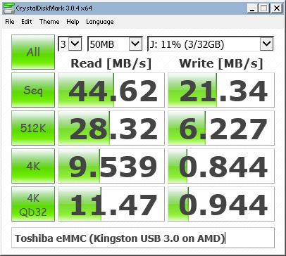
Toshiba THGBM4G9D8GBAII/064G4A benchmark in CrystalDiskMark

Toshiba THGBM4G9D8GBAII/064G4A benchmark in CrystalDiskMark

Although I was happy to get a usable benchmark score, my belief that all eMMC devices inherently had better 4K random I/O speeds than their SD counterparts was immediately busted. My guess is that random I/O wasn’t considered to be a priority until eMMC 4.5 or 5.0, and my eMMC modules are only version 4.41.

eMMC module listed as version 4.41

eMMC module listed as version 4.41

After the speed test, I ran the card through the popular Flash memory testing tool h2testw to make sure that I was not given a counterfeit device.

H2testw showing flash memory is good

H2testw showing flash memory is good

Excellent – it’s a genuine device. Despite the slower performance than expected, I’m happy that the memory capacity is as it should be.

“eMMC identification and CSD data, please”

As is the case with any USB memory card reader, I cannot access any of the eMMC device information (that is, the CID/Card Information Data and CSD/Card Specific Data registers). I took a spare SSD from my collection and got a quick Windows 10 installation running on one of my laptops that had a native SD host interface.
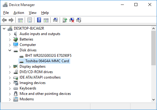
eMMC identified as Toshiba 064G4A MMC

eMMC identified as Toshiba 064G4A MMC

Interesting. The eMMC identifies itself as a Toshiba 064G4A MMC card. Googling that information brought up literally zero information, so it appears I’m the only one to have found (or published) any information about it. Although eMMCs support some degree of S.M.A.R.T. health reporting like mainstream SSDs and HDDs, no (easily-available) software (for Windows at least) is available to read it.

Linux has the ability to report the CID and CSD data as long as the native SD host interface is used, as opposed to a USB card reader.

CID: 11010030363447344100151344014e00
CSD: d00e00320f5903ffffffffef96400000
date: 04/2011
enhanced_area_offset: 18446744073709551594
erase_size: 8388608
fwrev: 0x0
hwrev: 0x0
manfid: 0x000011
oemid: 0x0100
preferred_erase_size: 8388608
prv: 0x0
raw_rpmb_size_mult: 0x2
rel_sectors: 0x10
serial: 0x15134401

With the help of Gough Lui’s CID and CSD decoders, I was able to gain some more information about the eMMC device, but not too much as the information I was originally interested in was already collected by this point.

Out of the Reader and Back Into the (CF) Adapter

Now that I know what the eMMC is capable of, I decided to try putting it back into my SD-to-CF adapter and doing another benchmark.
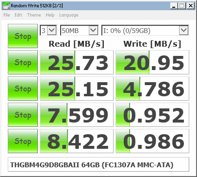
eMMC in FC-1307A SD-to-CF adapter. Note the limited performance of this chipset.

eMMC in FC-1307A SD-to-CF adapter. Note the limited performance of this chipset.

This test highlights one of the biggest limitations of the FC1306T/FC1307A chipset that so many adapters use: their performance is limited to a maximum of 25 MB/s per channel. Good thing I purchased that USB 3.0 reader…

Conclusion

This was quite the learning experience. I not only learned that eMMC flash memory does not necessarily have the near-SSD performance that the latest devices offer, but I learned how to “exploit” the unused pads of a BGA device as a sort of “prototype area” for soldering small components onto.

Did I save any money by rolling my own Flash storage device? Absolutely not – given how much time I spent on this, if I paid myself minimum wage ($12 per hour where I live), I could have bought at least three higher-performance 64GB SDXC cards with none of the frustration of trying to adapt an embedded memory device as a removable memory card. But where’s the fun in that? 🙂
Ramble: Fixstars’ 6TB SATA SSD – is it a thing?

If you know me personally, you’ll know that I absolutely love SSDs. Every PC I own has one, and I can’t stand to use a computer that runs off an HDD anymore. Naturally, when I read about a 6 TERABYTE SSD coming out, it piqued my curiosity.

Photo is owned by Fixstars and is not my property. Retrieved from http://www.fixstars.com/en/news/wp-content/uploads/2015/05/SSD-6000M.png

Official SSD-6000M promotional photo, taken from Fixstars’ press release

A Japanese company by the name of Fixstar has recently announced the world’s first 6TB SATA-based SSD. Although 2.5″ SSDs in such a capacity range already exist, they’re SAS (Serial Attached SCSI) based which limits them primarily to server/datacenter usage. According to Fixstars’ press release, their SSD-6000M supports sequential read speeds of 540 MB/s, and sequential write speeds of 520 MB/s, which is on par with most modern SATA III (6 Gbps) SSDs on the market today.

Concerns

However, after reading a bit online, I’m beginning to have some concerns about the drive’s real-world performance. One thing that is rather worrying is that the company has only mentioned sequential I/O speeds and has said nothing on random I/O or read/write latency; although SSDs do have much better sequential speeds than their mechanical spinning counterparts, they really shine when it comes to random I/O (which makes up much of a computer’s typical day-to-day usage). In the early, early days of SSDs, manufacturers cared only about sequential I/O and it resulted in some SSDs that were absolutely terrible when it came to random I/O (fun fact: I once had an early SSD, the Patriot PS-100, and its performance was so bad that it actually turned me off of SSDs for a few years, so I know how bad such unoptimized SSDs can perform).

Construction

The SSD appears to be made up of 52 eMMC (embedded MultiMediaCard) chips in a sort of RAID 0 configuration and an FPGA (field-programmable gate array) as the main controller. In layman’s terms, this SSD is literally made up of a bunch of SD cards “strapped” together with a chip so that it appears as one single drive. In that sense, one can make a similar solution using a board like this, which parallels multiple microSD cards to act as a single ‘SSD’.

Image retrieved from Amazon (http://ecx.images-amazon.com/images/I/51y0QqWL5sL.jpg)

The consumer equivalent of the SSD-6000M: SD cards and a controller chip. You can even get them from Amazon.

Conclusion

I’m wary of how well this SSD is going to take off. It could end up being a tremendous success, but it’ll certainly be out of the reach of the consumer market – either by its potentially poor random I/O performance, or its price (apparently it will cost well over $6000 USD).