As seen on Hackaday!
While on my quest for more eMMC-based storage devices, I stumbled upon a few devices that piqued my interest: eMMC-based SATA SSDs! I found two models of particular interest: Dell had M.2 modules with a 2.5″ adapter, and HP had custom boards intended for use in cheap laptops (for example, the HP 14-an012nr). Although the former was easier for me to use (but not acquire), I will be focusing on the latter in this blog post.
Overview of HP 14-am/14-an Series SSD Module
Unlike Dell’s convenient M.2 modules, the cheaper boards from HP (costing about $12 USD when I purchased them) had a physical interface intended for use only with its intended host; despite using a SATA interface, physically it used a 10-pin FFC (Flat Flexible Connector, aka “ribbon cable”) since it was designed to work only with HP’s 14-am/14-an series of low-cost laptops. The boards are labeled “DINERAMD-6050A2862201-DB-A01” and have a copyright date of 2016 in my case.
-
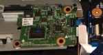
- HP eMMC SSD board in its natural habitat (courtesy of YouTube: https://www.youtube.com/watch?v=ulmmYmbwowY)
-
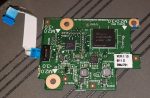
- Close-up of board
The BayHub OZ788WR2 Bridge Chip
These eMMC-based SSDs use a curious little chip, the BayHub OZ788WR2 (labeled 788WR2A on the chip itself). It is an SD/MMC-to-SATA adapter, with an SD UHS-II/MMCplus HS200 device interface and SATA II 3Gbps host interface. Apart from the brief description from the manufacturer, no other data is available for the chip (and even finding the chip online is basically impossible).
It’s a shame that so little is known about this chip (and that it’s so rare to find in actual devices), especially since high-performance SD-to-SATA adapters otherwise do not exist, as they use outdated SD-to-CompactFlash adapter chips that are limited to 25 MB/s speeds. If I had the engineering expertise, time, money, and ability to acquire these chips, I’d totally try to make an SD-to-SATA adapter with this chip… but alas, that will still remain a fantasy.
Step 1: Pinout Discovery
The single connector on the eMMC SSD is a ZIF FFC (Zero Insertion Force, Flat Flexible Connector), with no publicly available pinout or any other information. Perhaps this was why I got them for so cheap – apart from holding only 32 GB, nobody could even use them in their own computer even if they wanted to!
When trying to reverse engineer an unknown connector pinout, one needs to first look for ground pins. This is easily accomplished by using a multimeter with a continuity or diode test function, with the multimeter’s positive lead on a known ground point on the DUT (Device Under Test) – screw holes are often good candidates to look for. Ground pins will read as a short, but active IC and power pins will look like a forward-biased diode – appropriately 0.5 to 1 volt. I found 3 power pins (these are often grouped together on connectors for greater current capacity), 3 ground pins, and 4 SATA data pins. The data pins don’t show up on the multimeter test since they have series AC coupling capacitors, but they are easily located next to the connector and have clearly visible differential pairs leading to them.
The issue now is trying to find what order the SATA data pins are in, and how they relate to a regular SATA interface. As it turns out, the pinout is very simple: it matches the pinout of the 7-pin regular SATA interface! This makes sense as the SSD module and the laptop itself are designed to be cheap to manufacture.
-
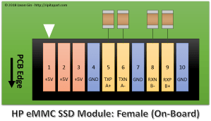
- Pinout for the HP eMMC-based SATA SSD module
Step 2: Building the Adapter (Take 1)
With the pinout known, the harder part is wiring up the connector. However, without a matching connector for the ribbon cable, I have no choice but to solder to it.
As I soon learned, not all flex cables are made of heat-resistant polyimide (aka Kapton) – this one melted before I could even tin the exposed leads. No matter, I’ll just use my trusty magnet wire and hook up the data and power lines! With the help of a salvaged SATA connector from a dead laptop drive, I was able to cobble together a crude adapter for the eMMC SSD board.
Although I didn’t end up taking a picture of the adapter, it wasn’t pretty. It also wasn’t very functional either – although the eMMC SSD board was able to identify itself (on my PC it showed up as a “BHT WR202HH032G E70211F5”), I couldn’t actually perform any data transfer without causing the OZ788WR2 to log hundreds of interface checksum failures (but hey, it supports S.M.A.R.T. data reporting!).
After some tweaking of the wire spacing, I was able to get the adapter stable enough to work, and encased it in hot glue for protection. It lasted a few weeks but eventually stopped working because one of the data wires broke off inside the blob of hot glue. Additionally, the outer contacts on the ribbon cable connector were peeling away from its plastic substrate. It was time for a rebuild.
Step 3: Building a Dedicated eMMC SSD (the teaser!)
Since I had multiple eMMC SSD boards, I took one, replaced the eMMC with a 128GB one from Samsung (the KLMDG8JENB-B041) and removed the ribbon cable connector. In its place, I used some very thin twinaxial cable from a dead MacBook and used a gutted CFast-to-SATA adapter for a shell. Stay tuned for that in another blog post!
Step 4: Building the Adapter (again!)
Much like my previous attempt, I used a salvaged PCB from a dead laptop drive, but left a lot of it instead of chopping it off directly at the connector. This particular one was a dead Samsung HDD, and it had one particular feature that I could use to make a stronger adapter: it had a TSOP footprint for the DRAM cache, which was just the right pitch for me to solder the ribbon cable to!
With a little help of my hot air rework station, I removed the DRAM cache and DC-DC converter, leaving the SATA AC coupling capacitors and the power input components (filtering choke and capacitors, and input overvoltage protection) behind.
After scraping off some solder mask, I soldered the SATA data wires and the ground wires surrounding them with very thin magnet wire, trying to keep the data pairs as close to each other as possible to minimize the chance of interference causing problems. The power wire was soldered to the power input components, right next to the input capacitor for better power delivery.
-
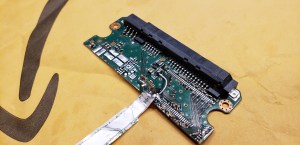
- Completed adapter for HP eMMC SSD board
-
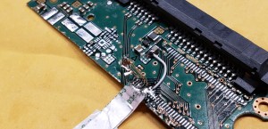
- Close-up image of connections and depopulated components
-
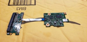
- Finished adapter with SSD board
After checking with the multimeter that no short circuits were present, I hooked up an eMMC board and plugged it into my PC. It enumerated without issues, and running several tests including CrystalDiskMark, h2testw, and Hard Disk Sentinel’s random read test, amassing several hundreds of gigabytes in reads and writes with zero CRC errors logged in the S.M.A.R.T. data.
-
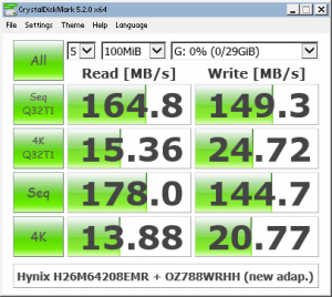
- Benchmark of SK Hynix H26M64208EMR eMMC 5.1 in CrystalDiskMark
-

- Benchmark of Samsung KLMBG2JENB-B041 eMMC 5.1 in CrystalDiskMark
With everything checked out, I cleaned the circuit with isopropyl alcohol and covered the exposed end of the ribbon cable and the magnet wires with clear epoxy for protection. I also used a bit of epoxy on the flex connector to re-secure the lifted contacts to the substrate.
Conclusion
With a bit of wire and a circuit board from a dead HDD, I was able to reuse cheap eMMC-based SATA SSDs on computers that they weren’t meant for (and they even had copies of Windows 10 Home with extractable license keys! 🙂 ). Although not as fast as a modern full-fledged SSD, its relatively high 4K IOPS performance means it works well enough as a quick boot drive for running quick tests of OS installation without needing to sacrifice a bigger drive just for testing – and they consume less than a watt even when fully active!
