Ramble: 2020 in review

It goes without saying that 2020 has turned out to be… less than optimal for most of us. The COVID-19 pandemic has wreaked havoc on virtually every facet of our lives, with innumerable losses around the world. Even with all the (involuntary) free time added due to local lockdown(s) and other social restrictions, I’ll admit that I haven’t made nearly as many blog posts this year as I would have liked. However, that doesn’t mean that people haven’t stopped reading my content – let’s see how this year has fared in that regard.

Top 5 Posts

Post Views
(New!) Reverse-engineering SanDisk’s High Endurance SD card 7,717
KitchenAid induction cooktop service manual 4,185
Building my own SD card with an eMMC chip 4,082
Resurrecting a dead MacBook Pro 3,649
SIM card PIN recovery with a logic analyzer 2,952

The one post that did make it out of the Drafts folder this year was my adventure in reverse-engineering a SanDisk high-endurance memory card in order to see what specific kind of NAND Flash was being used, earning over 7,500 views this year; these views primarily came from Hackaday, Twitter and Reddit.

The other posts are classics that people still love to read about. Once again, the KitchenAid service manual’s popularity indicates that KitchenAid/Whirlpool still hasn’t done anything to fix their faulty designs – and the comments suggest that the (ongoing as of the writing of this post) pandemic has made it even more difficult to get damaged cooktops serviced!

Views

This year ranks 5th out of 8 years of running my blog, amassing 102,420 views this year. Given the relative lack of featured posts on sites like Hackaday, this drop in views is largely expected – but I’m still happy to have surpassed the 100,000 view mark this year.

WordAds Performance

This year’s WordAds performance is the worst I’ve seen since I joined back in late 2017. Despite serving 933,470 ads this year, this only netted $98 USD, yielding a CPM (cost per 1,000 ad impressions) of merely $0.10! This is in stark contrast with even last year’s CPM of $0.24 – and that was already on a huge downslope! The lowest point was in June, with a CPM of merely $0.04, and a revenue of $5.21 respectively. However, the CPM rates have begun to improve to late 2019 levels since October.

Of course, this isn’t unexpected as the COVID-19 pandemic has decimated the world’s economy, and online advertisements are no exception. Consequently, this year’s revenue isn’t even enough to cover my hosting costs, but it still helps make running the blog less painful for my wallet.

Looking Forward

After this year’s tumultuous chain of events (and not being quite out of the woods in terms of COVID-19 vaccination and elimination), hopefully 2021 will be a reprieve after 2020’s parade of constant interruptions and unforeseen consequences. Hopefully the upcoming year will be a lot better for all of us. I want to get a lot of posts out of the Drafts folder, as I’ve been working on a lot of projects – but blog posts (sadly) don’t write themselves! Stay tuned…

Happy New Year! Here’s to hoping 2021 won’t be nearly as disastrous as 2020; once again, many thanks to everyone who reads and shares my blog posts – it means a lot to me! –Jason

eMMC Adventures, Episode 4: Recovering data from physically damaged BGA eMMC Flash storage chips

As seen on Hackaday!

The ball grid array (BGA) chip package has been instrumental in getting modern electronics to fit in smaller and smaller spaces, as it uses tiny balls of solder on the bottom of the package to make electrical connections, instead of copper leads on the edge of the chip package. This allows for hundreds of connections to be made in a small amount of PCB area, but their size also makes them very vulnerable to damage as well.

One common way for BGA chips to become damaged is called “pad cratering“, where the copper pad on the package’s substrate (basically a wafer-thin circuit board) separates and leaves behind a crater.

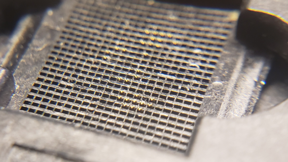
In the case of eMMC (Embedded MultiMediaCard), its package type is known as an FBGA (Fine-pitch Ball Grid Array), so the area of each pad is very small (0.4 mm in diameter!); it doesn’t take much at all to crater the pad – even gently removing solder with solder wick and generous amounts of flux can still cause damage! Most of the pads on an eMMC package are unused, but if any one of the DAT0, CLK, or CMD pads are damaged, then the chip is rendered unusable, even if the chip is placed into a socket for data recovery. If the DAT1-DAT7 pads are damaged, data recovery becomes much slower as the chip is forced to use fewer lines to transmit data (the MMC standard supports data over 1, 4, or 8 lines).

However, there is some hope. Many FBGA packages, including eMMC, use pads that are SMD (solder-mask defined); this means the solder mask is what defines the size of the pad, not the copper itself. Therefore, when the pad gets cratered, often there is a “halo” of copper left behind that still has a chance of getting an electrical connection.

The trick is how to to get a flat conductive area that a chip socket can use to get a reliable connection (without a copper pad, soldering is no longer an option). The eMMC socket adapter I used breaks out the eMMC onto an MMCplus-shaped PCB that can be inserted into any commercial SD card reader.

Filling in the Blanks

There are a few possible materials that can be used to restore contact area on a damaged BGA pad. One possible option is a silver-filled conductive epoxy, but I have not tested its efficacy; an additional consideration is that the volume of the filled-in crater might not be enough to get a filling with sufficiently low resistance for a good connection.

Another option is using solder paste, which I used in this case. Unfortunately, solder’s surface tension is our enemy when trying to fill in a flat area (it wants to form cohesive balls and therefore won’t want to stick to the ring of copper left around the crater), so a means of forcing the solder into the crater requires something flat, rigid and capable of handling the high temperatures experienced during soldering.

At first I tried Kapton (polyimide) tape, but that was a massive failure since it didn’t have the rigidity to stay flat when the solder paste began to melt, and the liquid flux rendered the adhesive useless.

The solution to the issue came in the form of glass. Specifically, I used very thin (0.15 mm thick!) glass “cover slips” normally used to prepare specimens for viewing under a microscope. These can be very inexpensive and one can obtain hundreds of them for a few dollars. The key is to fill the craters with the solder paste by using a knife as a squeegee, then placing the cover slip on top of the eMMC and reflowing it.

It took a few iterations for the pads on some of my eMMC chips to be restored sufficiently, as the volume taken up by the solder will be less than the paste and its accompanying flux. It doesn’t have to fill the entire crater – it just needs to be enough for the eMMC socket’s pins to make a solid connection.

Conclusion

The high-density nature of modern BGA chips is both a blessing and a curse. When trying to do data recovery from devices that use such tiny chips, such as eMMC or UFS Flash storage, sometimes the desoldering process is too much for the chip’s pads to handle. With some ingenuity (and thin glass), it might be possible to temporarily restore enough conductive pad area to get the data off with the help of an eMMC socket.

Status Update: Of Phones and Fire

Things might be on a bit of a hiatus for the next little while. My trusty Sony Xperia Z5 Compact literally went up in flames a few hours ago, and I need to find a replacement very soon, as well as recover any data that wasn’t saved to my SD card. Thankfully, apart from a sore throat and burning eyes from battery smoke, I am doing fine (as well as my house).

IMG_4711

My Sony Xperia Z5 Compact… after the lithium-ion battery fire.

Once things settle down, I’ll hopefully have a juicy story about lithium-ion battery fires and (failed) eMMC data recovery.

UPDATE (May 18, 2018): I upgraded to a Samsung Galaxy S9 a couple days ago. The eMMC chip I desoldered from the Z5 Compact is effectively bricked, as it only identifies itself but no data can be read – I suspect that the intense heat must have “baked” the NAND flash and result in too many uncorrectable bit errors that the firmware couldn’t recover from. There goes my progress in Angry Birds 2 (among other data)…

Tutorial: Recovering Cookie Clicker saves from an offline installation/backup of Google Chrome

Update (August 29, 2018): Turns out cleaning out your cookies/cache will erase your Cookie Clicker save. Who would’ve thought…

Cookie Clicker saves: You don’t realize the importance of saving your progress until you lose your save data. A few days ago I opened Chrome to my always-running instances of Cookie Clicker, but found that all of my progress was deleted (and it was showing a “Don’t forget to back up your save” message just to add insult to injury).

My heart sank when I realized that one of my runs, over three years old, had suddenly vanished into thin air. I tried restoring Google Chrome’s data via a Shadow Copy; no dice. I tried using my Windows Home Server 2011 backups, but realized that it would take over an hour to restore my Chrome folder. After much frustration, I decided to retrieve and examine Chrome’s Local Storage folder and see whether I could retrieve my save files that way – and it worked! Here’s how to recover your own Cookie Clicker saves…

Retrieving an older version of Google Chrome’s data folder

If you have Shadow Copy (aka Previous Versions) enabled, you may be in luck if the restore point(s) available have intact game save information. If you have an offline backup solution, that may be usable as well. If you have neither, you could try it on your current Chrome installation but your chances of recovery are much slimmer.

For Windows, Google Chrome’s default Local Storage folder located at: %USERPROFILE%\AppData\Local\Google\Chrome\User Data\Default\Local Storage

There will probably be a large number of files ending in .localstorage and .localstorage-journal – these are unlikely to contain your saves, and if they are present, they will be many months out of date; Google has begun storing websites’ local storage in a LevelDB database. The database in question is stored in a folder called leveldb.

If you are attempting to retrieve the data from a current Chrome installation, close Chrome before continuing.

Copy this “leveldb” folder to another (safe) location as to avoid any accidental overwrite of the database while trying to recover the game saves. Download and install the FastoNoSQL database browser software (it’s a trial, but for our purposes it will do just fine – just follow the registration instructions and you can whip up a temporary email address if you need to).

Browsing the LevelDB database

When FastoNoSQL is opened for the first time, the Connections window will appear. Click the “Add connection” button (it looks like a green button with a + symbol on it); even though we’re just browsing some database files, it’s considered to be a “connection” to the database. Select “LevelDB” and choose the folder that holds the “leveldb” folder that was previously copied.

Once the database is opened, note the number of database keys (in my case it was 1212), right-click the “default” database in the Explorer tree on the left-hand side of the FastoNoSQL window, and select “Load content of database”. Enter the number of keys previously noted into the “Keys count” field, then click OK.

In the “Search…” box, enter this text (select all the text in this box):

\\x5f\\x68\\x74\\x74\\x70\\x73\\x3a\\x2f\\x2f\\x6f\\x72\\x74\\x65\\x69\\x6c\\x2e\\x64\\x61\\x73\\x68\\x6e\\x65\\x74\\x2e\\x6f\\x72\\x67\\x00\\x01\\x43\\x6f\\x6f\\x6b\\x69\\x65\\x43\\x6c\\x69\\x63\\x6b\\x65\\x72\\x47\\x61\\x6d\\x65

This cryptic-looking text is a hexadecimal-escaped version of the string _https://orteil.dashnet.org, an SOH (Start of Header) character, and CookieClickerGame.

If your saves are found, you will see one or two entries, depending on whether or not the normal and/or Beta saves are present. The first entry will be the normal version of Cookie Clicker, and the second one, with a slightly longer key (ending in “\x42\x65\x74\x61”) is the for the Beta. Right-click the desired entry and choose “Edit…” to view the game save data. Copy the contents of the “Value” field into a text editor (Notepad, etc.), and delete the very first character before “Mi4w” – this is an SOH (Start of Header) character and we don’t need it to restore the game save. Save this text file so you have a backup of your game save, and import the file into Cookie Clicker (either by copy-pasting the text or using the “Load from file” button).

The game save should look like this (look for the bolded characters to ensure the game save data is intact):
Mi4wMDQ1fHwxNTI [... text omitted ...] OkwoDCgAR8%21END%21

If everything works out, your Cookie Clicker game save should be restored from the brink of destruction!

eMMC Adventures, Episode 2: Resurrecting a dead Intel Atom-based tablet by replacing failed eMMC storage

As seen on Hackaday!

Recently, I purchased a cheap Intel Atom-based Windows 8 tablet (the DigiLand DL801W) that was being sold at a very low price ($15 USD, although the shipping to Canada negated much of the savings) because it would not boot into Windows – rather, it would only boot into the UEFI shell and cannot be interacted with without an external USB keyboard/mouse.

The patient, er, tablet

The tablet in question is a DigiLand DL801W (identified as a Lightcomm DL801W in the UEFI/BIOS data). It uses an Intel Atom Z3735F – a 1.33GHz quad-core tablet SoC (system-on-chip), 16GB of eMMC storage and a paltry 1GB of DDR3L-1333 SDRAM. It sports a 4500 mAh single-cell Li-ion battery, an 8″ 800×1200 display, 802.11b/g/n Wi-Fi using an SDIO chipset, two cameras, one microphone, mono speaker, stereo headphone jack and a single micro-USB port with USB On-The-Go support (this allows the port to act as a USB host port, allowing connections with standard USB devices like keyboards, mice, and USB drives).

Step 1: Triage & troubleshooting

The first step was to power on the tablet to get an initial glimpse into the issues preventing the tablet from booting. I was able to confirm that the eMMC was detected, but did not appear to have any valid MBR or file system; therefore, the UEFI firmware defaulted to entering the UEFI shell (which was of little use on its own as there is no on-screen keyboard available for it).

DSC_2191

DigiLand DL801W with UEFI shell

However, one can immediately notice there is an issue with the shell: how do you enter commands without an on-screen keyboard? The solution was to use a USB OTG (On-The-Go) dongle to convert the micro-USB type B port into a USB type A host port.

Using the shell commands, I tried reading the contents of the boot sector, which should end with an MBR signature of 0x55AA. Instead, the eMMC returned some nonsensical data: the first half of the sector had a repeating byte pattern of 0x10000700,  and the second half was all zeroes (0x00) except the last 16 bytes which were all ones (0xFF). The kicker was that this data was returned for every sector I tried to read. No wonder the eMMC was unbootable – the eMMC had suffered logical damage and the firmware was not functioning correctly.

After creating a 32-bit Windows 10 setup USB drive (these cheap low-RAM PCs often use a 32-bit UEFI despite having a 64-bit capable CPU), I opened Hard Disk Sentinel to take a deeper look at the condition of the onboard eMMC.

DSC_2198

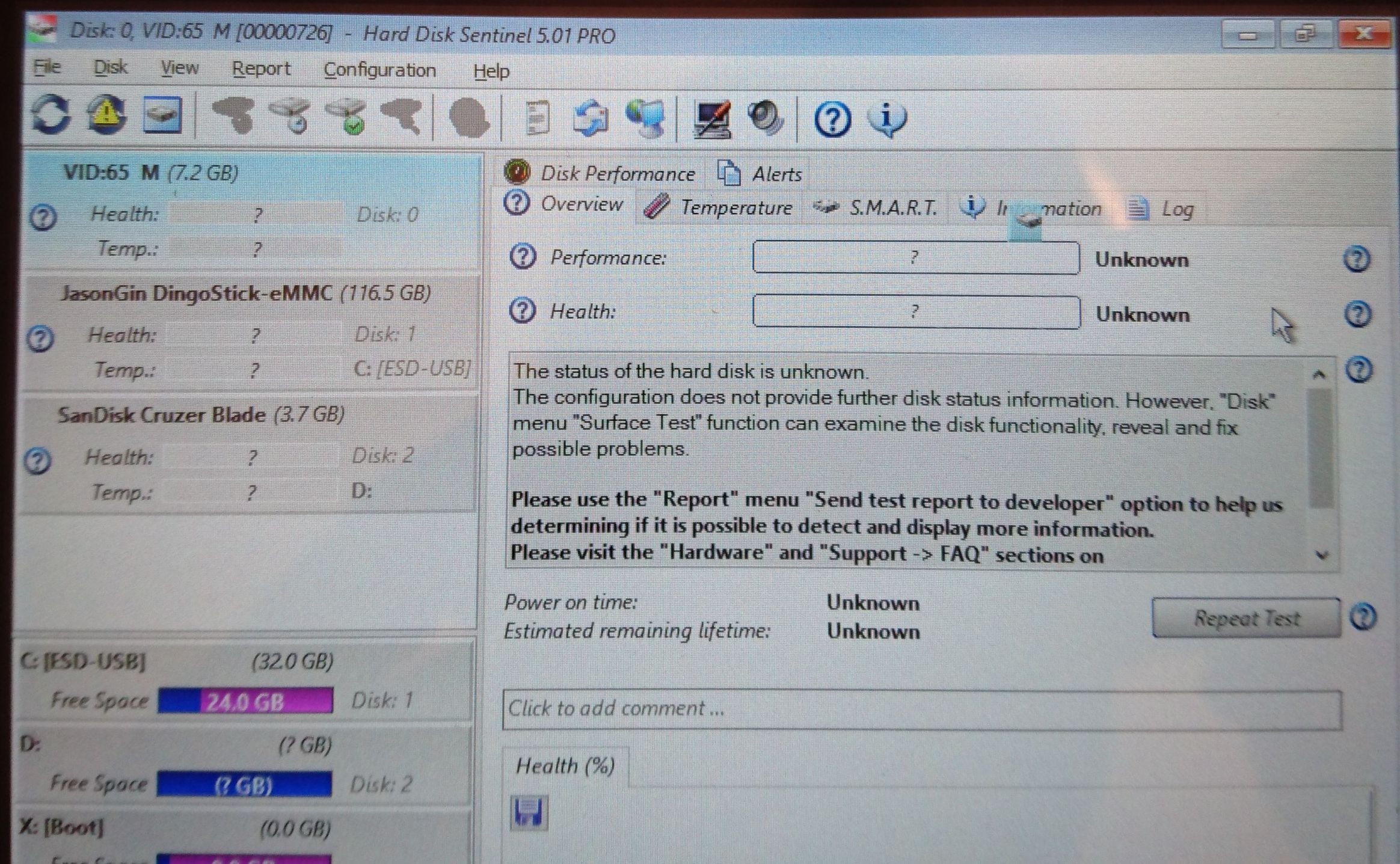
Malfunctioning Foresee 16GB eMMC visible in Hard Disk Sentinel

The eMMC identified itself with a vendor ID of 0x65, and an MMC name of “M”. It reported a capacity of 7.2 GB instead of the normal 16 GB, another sign that the eMMC was corrupted at the firmware level.

DSC_2199

Foresee 16GB eMMC returning corrupted data

Using HDS, I performed a read scan of the entire eMMC despite its failed condition. The read speeds were mostly consistent, staying between 40 to 43 MB/s. A random read test revealed a consistent latency of 0.22 ms.

In order to assess whether the eMMC was writable in its current state, I ran a zero-fill and subsequent read scan. The eMMC appeared to accept writes but did not actually commit them, as HDS threw verification errors for all sectors.

After the tests in HDS, I decided to attempt an installation onto the eMMC to assess its writability. Windows Setup failed to create the disk partition structures, throwing an error message reading “We couldn’t create a new partition or locate an existing one”.

Step 2: Teardown & eMMC replacement

Since the onboard Foresee NCEMBS99-16G eMMC module was conclusively determined to be faulty, there was no point keeping it on the tablet’s motherboard. This also provided an opportunity to upgrade the eMMC to a a larger and faster one. Since this required the tablet to be disassembled, I decided to do a teardown of the tablet before attempting to replace the failed eMMC module (the teardown will be in a separate blog post when the time comes).

After removing the insulating plastic tape on the bottom of the PCB, I masked off the eMMC with some kapton tape to protect the other components and connectors from the heat of my hot-air rework station. With some hot air and patience, the failed Foresee eMMC was gone. This also revealed that the eMMC footprint supported both the 11.5×13 mm and 12×16 mm sizes, but the 12×16 mm footprint did not have the extra 16 solder balls for reinforcement (most eMMC balls are unused so their omission had no negative functional effect).

DSC_2215

Foresee eMMC removed from DL801W’s motherboard

Instead of a barely-usable 16 GB of eMMC storage, I opted to use the Samsung KLMBG4GEND-B031 – a 32 GB eMMC 5.0 module. This chip boasts more than 2000 IOPS for 4K random I/O, which should be a boon for OS and application responsiveness.

DSC_2219

Replacement Samsung KLMBG4GEND-B031 eMMC installed

A little flux and hot air was all I needed to give the 32 GB eMMC a new home. Time to reassemble the tablet and try installing Windows 10 again.

Step 3: OS reinstallation

After spending a few minutes cleaning the board and reinstalling it in the tablet, it was time to power the tablet back on, confirm the presence of the new eMMC and reattempt installing Windows.

DSC_2221

Installing Windows 10 from USB drive via USB-OTG adapter

The eMMC replacement proved to be successful; within minutes, I was off to the races with a clean installation of Windows 10.

Conclusion

DSC_2223

DL801W restored, running Texas Instruments’ bqSTUDIO software

This was a pretty fun project. With some electronics and computer troubleshooting skills, I had a tablet capable of running desktop Windows programs. Its low power consumption and USB host capabilities made for a great platform to run my Texas Instruments battery hardware and software without being tethered to my desktop.

However, I was not finished with this tablet. The 1 GB of onboard RAM made Windows painfully slow to use, as the CPU was constantly bogged down performing memory compression/decompression. The 32GB of eMMC storage I initially installed began feeling cramped, so I moved to a roomier 64GB (then 128GB) eMMC.

I won’t go into the details of how I upgraded the RAM in this post, as it’s a long story; simply put, soldering the RAM ICs was the easy part.

eMMC Adventures, Episode 1: Building my own 64GB memory card with a $6 eMMC chip

As seen on Hackaday!

There’s always some electronics topic that I end up focusing all my efforts on (at least for a certain time), and that topic is now eMMC NAND Flash memory.

Overview

eMMC (sometimes shown as e.MMC or e-MMC) stands for Embedded MultiMediaCard; some manufacturers create their own name like SanDisk’s iNAND or Hynix’s e-NAND. It’s a very common form of Flash storage in smartphones and tablets, even lower-end laptops. The newer versions of the eMMC standard (4.5, 5.0 and 5.1) have placed greater emphasis on random small-block I/O (IOPS, or Input/Output operations per second; eMMC devices can now provide SSD-like performance (>10 MB/s 4KB read/write) without the higher cost and power consumption of a full SATA- or PCIe-based SSD.

MMC and eMMC storage is closely related to the SD card standard everyone knows today. In fact, SD hosts will often be able to use MMC devices without modification (electrically, they are the same, but software-wise SD has a slightly different feature set; for example SD cards have CPRM copy protection but lack the MMC’s TRIM and Secure Erase commands. The “e” in eMMC refers to the fact that the memory is a BGA chip directly soldered (embedded) to the motherboard (this also prevents it from being easily upgraded without the proper tools and know-how.

When browsing online for some eMMC chips to test out, I found a seller that had was selling 64 GB eMMC modules for $6 Canadian per pop; this comes out to a very nice 9.375 cents per gigabyte (that’s HDD-level pricing right there!). With that in mind, I decided to buy a couple modules and see what I could do with them. A few days later, they arrived in the mail (and the seller was nice enough to send three modules instead of just two; the third module’s solder balls were flattened for some reason).

Toshiba eMMC Module

Toshiba THGBM4G9D8GBAII eMMC 4.41 modules

Toshiba THGBM4G9D8GBAII eMMC 4.41 modules

The Flash memory I used is a Toshiba THGBM4G9D8GBAII. According to a Toshiba NAND part number decoder:

  • TH: Toshiba NAND
  • G: Packaged as IC
  • B: Vcc (Flash power supply) = 3.3 V, VccQ (controller/interface power supply) = 1.8 or 3.3 V
  • M: eMMC device
  • 4: Controller revision 4
  • G9: 64 GB
  • D: MLC NAND Flash
  • 8: Eight stacked dice (eight 8 GB chips)
  • G: 24nm A-type Flash (appears to indicate Toggle Mode interface NAND)
  • BA: Lead-free and halogen-free
  • I: Industrial temperature grade (-40 to 85 degrees Celsius)
  • I: 14 x 18 x 1.2 mm BGA package with OSP (Organic Solderability Preservatives)

Given the low, low price of the eMMC chip, I had to make sure that I wasn’t given counterfeit Flash memory (often fake flash would have only 4 or 8 actual GB usable, with most of the address space looping over itself, causing data loss with extended usage). This involved find a way to temporarily connect the eMMC to my computer. I had a USB 2.0 SD/MMC reader on hand as well as a laptop with a native SD host interface, so now all I needed to do was break out the eMMC signals on the BGA package so that I can connect it to the reader.

eMMC Pinout… or is it Ball-Out?

There are plenty of pinouts for eMMC on the Internet, but they all show the pinout for a top view. Since I’m not soldering the eMMC to a PCB, I need to get a bottom view. I took a pinout diagram from a SMART Modular Technologies eMMC datasheet, rotated it to a landscape view, flipped it vertically, then flipped each row’s text in order to make it readable again. I then copy-pasted this into PowerPoint and traced out the package and ball pinouts. This allowed me to colour-code the different signal and power lines I’ll need to implement, including the data, clock, command and power lines. Curiously enough, one of the ground pins (VssQ, or controller/MMC I/O ground) was not a ground pin like the standard required; because of this, I decided to leave that pin open-circuit. Additionally, there were several pins that were not open-circuit, but did not have a known purpose either (these are probably used as test pads for the internal NAND Flash interface – perhaps they could be reused as raw NAND with the right controller, but the exact purpose of these pads will need to be reverse engineered).

Toshiba THGBM4G9D8GBAII eMMC pinout (solder balls facing up)

Toshiba THGBM4G9D8GBAII eMMC pinout (solder balls facing up)

eMMC Reader: Take 1 (Failed!)

For the first reader, I cut open a microSD-to-SD adapter, exposing the eight pins inside. I soldered a cut-up UDMA IDE cable and glued them in place. Despite my careful work, I still melted a hole through the thin plastic shell of the adapter; thankfully this did not affect the adapter’s ability to be plugged in.

I used double-sided foam adhesive tape and a piece of perfboard to create a small “test bed” for the eMMC module. Using some flux, solder wick, and a larger soldering iron tip, I removed all the (lead-free) solder balls on the center of the IC and replaced them with leaded solder bumps to make soldering the tiny 40-gauge magnet wire easier.

After bringing out the minimum wires required (VCC/VCCQ, GND, CLK, CMD, and DAT0 for 1-bit operation), I soldered the wires of my quick SD adapter, and plugged it into the SD card slot of a (very old) Dell Inspiron 9300.

Calling this board’s operation flaky doesn’t do it justice. It would fail to enumerate 9 out of 10 times, and if I even tried to do anything more than read the device capacity, the reader would hang or the eMMC would drop off the SD/MMC bus and show an empty drive in Windows. It was clear I had to do a full memory card “build” before I could verify the usability of the eMMC Flash memory.

eMMC in an SD Card’s Body: Take 1 (Success… half of the time)

I had a 16 MB (yes, megabyte) SD card lying around somewhere, but as usual, I couldn’t find it among all the clutter around my desk and workspace. Instead, I found an old, slow Kingston 2 GB SD card that I felt would be a worthy “sacrifice” since it was an older type that still had a thin PCB inside (most SD cards nowadays are monolithic, which means it’s one solid chunk with a few pads exposed). After opening up the case carefully with an Exacto knife, I wiggled out the old PCB. I desoldered the orignal 2 GB NAND Flash, and began work on breaking the SD card controller from the PCB as it was a chip-on-board design. It took a while, but I was able to ensure that none of the old SD card hardware would interfere with my rebuild.

I removed the eMMC from the board I made previously, and tested the thickness of it to ensure that it would fit inside the SD card case. It did, although the 0402 surface-mount decoupling capacitors I intended to install would cause a few bumps to be visible through the thin plastic SD card casing.

With my eMMC and SD card pinouts on hand, I used a small bead of epoxy to affix the eMMC to the PCB, balls-side up. I used magnet wire to connect the data lines (4 wires for 4-bit operation which is the maximum that the SD standard supports), and used the unused pads on the eMMC as a kind of prototyping space where I could install ceramic capacitors as close to the module as possible. I used a 0.1 µF 0402 size ceramic capacitor across the VDDi (eMMC internal regulator) and a neighouring GND pad. The rest of the power pads were wired in parallel with a few extra 0.1 µF capacitors added. I made use of the existing three 1 µF capacitors on the PCB as both extra decoupling and connection points for VCC and VCCQ. To prevent shorting of the inner CMD and CLK pins, I only removed the enamel coating from the magnet wire at the very end so I could solder them but avoid the issue of shorting those pins against the other signal and power lines. I then soldered these wires to the terminals on the other side of the PCB.

After spending about ten minutes wriggling the PCB into the SD card casing without damaging the wires, I used a multimeter to ensure all the pins were connected (use a multimeter in diode mode, with the positive lead connected to ground – any valid pins should read ~0.5 volts), and also ensured that there were no polarity reversals or shorts on the power pins.

Now… the moment of truth. At this point my USB 2.0 card reader still wasn’t cooperating with me, so I tried the only other ‘fast’ reader I had at the time – an SD to CompactFlash adapter.

To my relief, I finally got a (mostly) usable card. It appears this particular model has been pre-formatted with FAT32. Viewing the MBR in Hard Disk Sentinel shows nothing notable, apart from the fact that it’s pretty blank and is indicative that it wasn’t formatted for use as a PC boot medium.

Things began to fall apart after I tried running speed tests, as the card would hang if it experienced a lot of write activity at once. I suspected this was a power supply-related issue, so I modified my layout to add more capacitance. For good measure, I added 56 ohm termination resistance for the DAT0-4 data lines, using a small resistor network harvested from an old dead MacBook motherboard.

After these modifications, performance was much, much better. Now that the card was usable, I could finally run some speed tests.

eMMC in an SD Card’s Body – This time, with more feeling decoupling!

After adding several 100 nF and 1uF 0402-size ceramic capacitors on the eMMC package, I was able to get a stable card that could be read by (most) SD card readers. As I was rather anxious to get a decent benchmark from the eMMC, I decided to forego the cheaper Amazon Prime route, and go to my local PC parts store to buy a USB 3.0 card reader – the Kingston FCR-HS4.

After placing the eMMC and SD card PCB back into its plastic casing, I was relieved to see that Windows immediately recognized its presence. All I had to do then was open CrystalDiskMark and run the benchmark. Drum roll please…

Toshiba THGBM4G9D8GBAII/064G4A benchmark in CrystalDiskMark

Toshiba THGBM4G9D8GBAII/064G4A benchmark in CrystalDiskMark

Although I was happy to get a usable benchmark score, my belief that all eMMC devices inherently had better 4K random I/O speeds than their SD counterparts was immediately busted. My guess is that random I/O wasn’t considered to be a priority until eMMC 4.5 or 5.0, and my eMMC modules are only version 4.41.

eMMC module listed as version 4.41

eMMC module listed as version 4.41

After the speed test, I ran the card through the popular Flash memory testing tool h2testw to make sure that I was not given a counterfeit device.

H2testw showing flash memory is good

H2testw showing flash memory is good

Excellent – it’s a genuine device. Despite the slower performance than expected, I’m happy that the memory capacity is as it should be.

“eMMC identification and CSD data, please”

As is the case with any USB memory card reader, I cannot access any of the eMMC device information (that is, the CID/Card Information Data and CSD/Card Specific Data registers). I took a spare SSD from my collection and got a quick Windows 10 installation running on one of my laptops that had a native SD host interface.
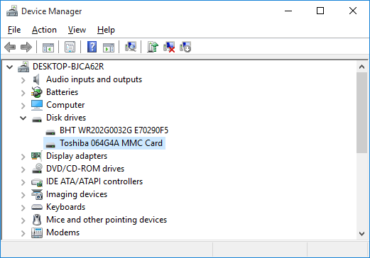
eMMC identified as Toshiba 064G4A MMC

eMMC identified as Toshiba 064G4A MMC

Interesting. The eMMC identifies itself as a Toshiba 064G4A MMC card. Googling that information brought up literally zero information, so it appears I’m the only one to have found (or published) any information about it. Although eMMCs support some degree of S.M.A.R.T. health reporting like mainstream SSDs and HDDs, no (easily-available) software (for Windows at least) is available to read it.

Linux has the ability to report the CID and CSD data as long as the native SD host interface is used, as opposed to a USB card reader.

CID: 11010030363447344100151344014e00
CSD: d00e00320f5903ffffffffef96400000
date: 04/2011
enhanced_area_offset: 18446744073709551594
erase_size: 8388608
fwrev: 0x0
hwrev: 0x0
manfid: 0x000011
oemid: 0x0100
preferred_erase_size: 8388608
prv: 0x0
raw_rpmb_size_mult: 0x2
rel_sectors: 0x10
serial: 0x15134401

With the help of Gough Lui’s CID and CSD decoders, I was able to gain some more information about the eMMC device, but not too much as the information I was originally interested in was already collected by this point.

Out of the Reader and Back Into the (CF) Adapter

Now that I know what the eMMC is capable of, I decided to try putting it back into my SD-to-CF adapter and doing another benchmark.

eMMC in FC-1307A SD-to-CF adapter. Note the limited performance of this chipset.

eMMC in FC-1307A SD-to-CF adapter. Note the limited performance of this chipset.

This test highlights one of the biggest limitations of the FC1306T/FC1307A chipset that so many adapters use: their performance is limited to a maximum of 25 MB/s per channel. Good thing I purchased that USB 3.0 reader…

Conclusion

This was quite the learning experience. I not only learned that eMMC flash memory does not necessarily have the near-SSD performance that the latest devices offer, but I learned how to “exploit” the unused pads of a BGA device as a sort of “prototype area” for soldering small components onto.

Did I save any money by rolling my own Flash storage device? Absolutely not – given how much time I spent on this, if I paid myself minimum wage ($12 per hour where I live), I could have bought at least three higher-performance 64GB SDXC cards with none of the frustration of trying to adapt an embedded memory device as a removable memory card. But where’s the fun in that? 🙂

Performance analysis/review of Kentli PH5 Li-ion 1.5V AA battery

In my previous blog post, I tore down the Kentli PH5 battery – a Li-ion battery that has an internal 1.5-volt regulator that allows for terrific voltage stability… up to a point. In terms of data collection, so far I have collected 55+ runs of data logs (248 MB of text files!) and still do not quite have all the data I want. As for the data that I do have, I will be disseminating them with as much thoroughness as possible.

Updated (May 1, 2018):

The battery’s self-discharge rate experiment has come to its conclusion – click here to read it.

I forgot to add a diagram of my test setup – here’s a Visio diagram of the hardware used to test the battery’s performance… Click here to see the full-sized diagram.

ph5 cycle test setup diagram


Voltage vs. load current

As expected, the voltage output of the PH5 remains quite stable, up until roughly 2.1 amps where the voltage sags noticeably until the regulator goes into overcurrent protection mode.

A maximum load capacity of 2.1 amps seems to be a bit… limiting. That said, I have not done tests on the PH5’s transient load capacity, as it would require more automated control than what I currently have available.

Another issue with having such a flat discharge curve is that any device that performs fuel gauging using voltage alone will report 100% capacity, until it suddenly shuts down. This could be a big problem for digital camera users, as they will have no indication that their batteries are running low, until the device abruptly stops working. If the camera was writing an image to its memory card when the battery died, it could cause the image to be corrupted, or worse, damage the file system on the card!

Voltage vs. state-of-charge

Unless you are running the battery at a high discharge rate, the output voltage will be flat at 1.5 volts before abruptly brickwalling and dropping to zero immediately at the end of discharge. At a high load (in the case of the graph below, at 2 amps), the voltage remains flat until the very end of the discharge cycle (99% depth of discharge for my test run), where it quickly tapers off and drops to zero.

Capacity vs. load

This is the big one, and it took a lot of work to get this data, especially at low loads (48+ hours of continuous logging is just asking for Murphy’s Law to come into play). I used almost 50 discharge runs to create the graph below.

This is where things get… interesting. I was expecting the capacity to peak at low currents then taper off as the load current increases. Instead, I noticed a definite ‘hump’ in capacity around the 250 mA mark (reaching a maximum of 1700 mAh / 2550 mWh), and only after that point did I see the expected downward slope in capacity, reaching 1200 mAh (1800 mWh) at the 2 amp mark.

This data brings forth some very interesting conclusions. The PH5’s capacity is inferior to its Ni-MH counterparts (even the relatively crappy ones), and at higher discharge rates it has similar capacity to that of an alkaline at the same load, albeit with much better voltage stability than the Ni-MH or alkaline chemistries.

Other findings

Although I won’t go into too much detail for the next few points (I haven’t gotten quite enough data to be presentable), there are some other issues with the battery that I think should still be mentioned.

One issue is the amount of heat the battery gives off at high loads. At 2.1 amps, I had to use a fan to blow cool air onto the DC-DC converter just to prevent it from entering its over-temperature shutdown mode. Although the converter itself can tolerate elevated temperatures, the Li-ion cell inside will not; the uneven heating that the cell will encounter could potentially degrade its lifespan in the long run.

Another problem is efficiency. At 1 amp, the DC-DC converter is about 75% efficient, and is only 65% efficient at 2 amps. I have not tested the converter’s efficiency at lower loads yet, but I doubt it will achieve more than 85-90% efficiency.

A potential issue with this battery is self-discharge. The buck converter remains active all the time, unless the converter or the Li-ion protection circuit enters a protective shutdown state. I have not had a chance to fully charge an unmodified battery in order to perform a long-term self-discharge test, but I will create another blog post for that, if/when the time comes. Update (May 3, 2018): See the top of the page for the link to the self-discharge test results.

Conclusion

Overall, I’m on the fence when it comes to this battery. Its innovative design does provide unparalleled voltage stability, but its low capacity even at moderate discharge rates dampens the fun significantly. Additionally, the 2.1 amp discharge limit could prove to be a bottleneck for some high-drain applications; this, coupled with the cell’s tendency to shut down abruptly when the internal cell runs empty could potentially cause file system corruption for digital cameras that have not been designed to handle such sudden power interruptions.

Also, the batteries are very costly. At about $10 per cell, you may want to think twice about replacing all your current disposable and rechargeable batteries with these newfangled Li-ion ones. Don’t forget the charger either, as a special charger is required to make contact with a recessed terminal on the top of the battery.

Overall, this cell is… interesting. Just don’t expect a miracle in a steel can.

Pros:

  • Excellent voltage stability, even at high loads
  • Li-ion chemistry allows for a very lightweight cell, even with the addition of a DC-DC converter
  • High output voltage could allow some devices to run more efficiently

Cons:

  • Low capacity – provides a mere 1200 mAh (1800 mWh) @ 2 amps, and up to 1700 mAh (2550 mWh) @ 250 mA (even alkaline batteries can do better than this)
  • Abrupt shutdown when the battery is overloaded, overheated, or over-discharged
  • Runs hot at high loads (and therefore is fairly inefficient)
  • 1.5 MHz converter and unshielded inductor can cause excessive EMI (electromagnetic interference) in sensitive devices
  • Expensive! Costs approximately $10/cell
  • Requires proprietary charger

Bottom Line: This is a niche product and should not be considered a universal replacement for alkaline or Ni-MH AA batteries.

Ramble: Fixstars’ 6TB SATA SSD – is it a thing?

If you know me personally, you’ll know that I absolutely love SSDs. Every PC I own has one, and I can’t stand to use a computer that runs off an HDD anymore. Naturally, when I read about a 6 TERABYTE SSD coming out, it piqued my curiosity.

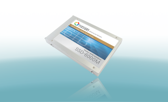
Photo is owned by Fixstars and is not my property. Retrieved from http://www.fixstars.com/en/news/wp-content/uploads/2015/05/SSD-6000M.png

Official SSD-6000M promotional photo, taken from Fixstars’ press release

A Japanese company by the name of Fixstar has recently announced the world’s first 6TB SATA-based SSD. Although 2.5″ SSDs in such a capacity range already exist, they’re SAS (Serial Attached SCSI) based which limits them primarily to server/datacenter usage. According to Fixstars’ press release, their SSD-6000M supports sequential read speeds of 540 MB/s, and sequential write speeds of 520 MB/s, which is on par with most modern SATA III (6 Gbps) SSDs on the market today.

Concerns

However, after reading a bit online, I’m beginning to have some concerns about the drive’s real-world performance. One thing that is rather worrying is that the company has only mentioned sequential I/O speeds and has said nothing on random I/O or read/write latency; although SSDs do have much better sequential speeds than their mechanical spinning counterparts, they really shine when it comes to random I/O (which makes up much of a computer’s typical day-to-day usage). In the early, early days of SSDs, manufacturers cared only about sequential I/O and it resulted in some SSDs that were absolutely terrible when it came to random I/O (fun fact: I once had an early SSD, the Patriot PS-100, and its performance was so bad that it actually turned me off of SSDs for a few years, so I know how bad such unoptimized SSDs can perform).

Construction

The SSD appears to be made up of 52 eMMC (embedded MultiMediaCard) chips in a sort of RAID 0 configuration and an FPGA (field-programmable gate array) as the main controller. In layman’s terms, this SSD is literally made up of a bunch of SD cards “strapped” together with a chip so that it appears as one single drive. In that sense, one can make a similar solution using a board like this, which parallels multiple microSD cards to act as a single ‘SSD’.

Image retrieved from Amazon (http://ecx.images-amazon.com/images/I/51y0QqWL5sL.jpg)

The consumer equivalent of the SSD-6000M: SD cards and a controller chip. You can even get them from Amazon.

Conclusion

I’m wary of how well this SSD is going to take off. It could end up being a tremendous success, but it’ll certainly be out of the reach of the consumer market – either by its potentially poor random I/O performance, or its price (apparently it will cost well over $6000 USD).

A Little Pick-Me-Up: Samsung 840 EVO SSD slowdowns, and how to fix it (for now…)

There’s been word going around that Samsung’s 840 EVO solid-state drives have an issue where they become really, really slow to read if the data on it has been sitting around for a few months, and I can confirm this is the case as well.

The first half of the drive (which holds a fair amount of static data) was being read at around 30 MB/s, with newer data being read at almost 500 MB/s. That’s a pretty big difference. One thing to note (I didn’t take a screenshot for this) is that although the overall read speed was significantly affected, the read latency was only somewhat slower; only about 10-20 microseconds of extra latency.

To temporarily fix this (at least until Samsung releases a firmware update in the middle of October), I used Hard Disk Sentinel to read and rewrite all of the data on the SSD. Because this involves accessing data that is normally locked by Windows, I made a custom WinPE (a slimmed-down, portable version of Windows that’s used for installation and recovery) image with Hard Disk Sentinel inside it. This allowed me to boot outside of the normal Windows setup, and perform the Read+Write+Read test to refresh all of the data stored on the SSD. Note that this will impart a lot of write activity to the NAND flash in the SSD (hence a chance for increasing wear), but modern SSDs aren’t as delicate as people might think.

HD Sentinel's Refresh Data Area test

Hard Disk Sentinel’s “Refresh Data Area” test

This took about 2 hours on my 250 GB SSD. Afterwards, another read test showed that the drive was working smoothly again.

Will I still buy a Samsung SSD? Absolutely. No data was lost and Samsung did the right thing by acknowledging the issue and also finding a way to fix it, as opposed to simply calling it a non-issue and sweeping it under the rug.

Looking inside a (fake) iPhone 5S battery

Considering how popular the iPhone is, there’s always going to be some counterfeits out there. I’ve been out buying various iPhone batteries to build a database of each generation’s characteristics, but one model has eluded me so far: the iPhone 5S. The iPhone 5C’s battery that I bought appears to be genuine (but with its own issues), but none of the iPhone 5S batteries I’ve bought so far (4 of them at the time of writing this blog post) were genuine. All of these fakes look like a genuine battery at first glance, but all of them share a few common traits.

Battery teardown

The fake battery sports the usual iPhone battery information, complete with some dot-matrix printed data and a data-matrix barcode. It’s labeled with a capacity of 1560 mAh and 3.8 volts nominal voltage.

Comparison between real and fake iPhone 5S battery

Comparison between real and fake iPhone 5S battery

The connector itself has two points for soldering the connector to provide durability. However, with the fake batteries, they are not soldered down. The two spots on the ends of the connectors are dark with a small point visible inside it (that point is the reinforcement pin on the connector). If this connector is installed in an iPhone, it will probably not come out without either damaging the battery’s connector, or worse, leave the plastic connector piece inside the phone, requiring tweezers to remove.

Connector lifted off with a hobby knife

Connector lifted off with a hobby knife

iPhone 5S and 5C battery pinout

iPhone 5S and 5C battery pinout

Removing the black protective tape reveals an iPhone 4 battery fuel gauge board. The connector is soldered to this board, with four solder points visible.

iPhone 4 battery PCB with soldered-on flat flex connector

iPhone 4 battery PCB with soldered-on flat flex connector

Pulling out the PCB  reveals another characteristic of these fake batteries: the positive terminal is cut short, with another metal section being clumsily spot-welded to the stub on the cell.

Note how the battery tab is poorly welded to the PCB.

Note how the battery tab is poorly welded to the PCB.

Battery fuel gauge data

The battery fuel gauge requires proper programming to accurately indicate the battery’s charge status. Because of this, each iPhone battery generation has its own specific configuration.

The fake iPhone battery retains the programming for the iPhone 4’s battery, which is a designed capacity of 1420 mAh, using a bq27541 fuel gauge running version 1.25 firmware. The data inside it is often that of a used/recycled battery as well.

This data can be (partially) read out directly from the iPhone with a tool such as iBackupBot, but more data can be read if the battery is read with another tool. I have the EV2400 from Texas Instruments to read this out on a PC, but this data can be read out with a USB-to-TTL serial port, a logic gate (a logic inverter) and a small MOSFET transistor.

I created a small tool that uses this circuit to interface with the fuel gauge and read out its data. Check it out here.

Using my tool, this is the report for one of these fake batteries. Note how it is identified as an iPhone 4 battery. Don’t be fooled by the calculated state of health. It’s not accurate for this battery as the fuel gauge still thinks it’s still inside an iPhone 4 battery pack.


**** START OF HDQ BATTERY LOG REPORT ****
HDQ Gas Gauge Readout Tool version 0.9 by Jason Gin
Date: 9/30/2014
Time: 0:52:24
Serial port: COM26

Battery Identification
========================
DEVICE_TYPE = 0x0541, FW_VERSION = 0x0125, DESIGN_CAPACITY = 1420 mAh
Battery's configuration matches that of a standard iPhone 4 battery.

Basic Battery Information
===========================
Device = bq27541 v.1.25, hardware rev. 0x00B5, data-flash rev. 0x0000
Voltage = 3804 mV
Current = 0 mA
Power = 0 mW
State of charge = 45%
Reported state of health = 0%
Calculated state of health = 99.3%
Cycle count = 14 times
Time to empty = N/A (not discharging)
Temperature = 27.9 °C (80.3 °F) (3009 raw)
Designed capacity = 1420 mAh
Heavy load capacity = 628/1410 mAh
Light load capacity = 673/1455 mAh

Advanced Battery Information
==============================
Capacity discharged = 0 mAh
Depth of discharge at last OCV update = ~778 mAh (8768 raw)
Maximum load current = -200 mA
Impedance Track chemistry ID = 0x0163
Reset count = 11 times

Flags = 0x0180
Flag interpretation:
* Fast charging allowed
* Good OCV measurement taken
* Not discharging

Control Status = 0x6219
Control Status interpretation:
* SEALED security state
* SLEEP power mode
* Constant-power gauging
* Qmax update voltage NOT OK (Or in relax mode)
* Impedance Track enabled

Pack Configuration = 0x8931
Pack Configuration interpretation:
* No-load reserve capacity compensation enabled
* IWAKE, RSNS1, RSNS0 = 0x1
* SLEEP mode enabled
* Remaining Capacity is forced to Full Charge Capacity at end of charge
* Temperature sensor: External thermistor

Device name length = 7 bytes
Device name: bq27541

**** END OF HDQ BATTERY LOG REPORT ****

Looking inside an iPhone 5 battery

In the wake of my previous teardowns of the iPhone 4 and 4S batteries, I went onto eBay and Amazon (realizing that they finally have Amazon Prime student rates up in Canada) and bought a few iPhone 5 and 5S batteries. Although I was primarily interested in trying to get the gas gauge information out of the batteries, I had a secondary reason. The Nexxtech Slim Power Bank (a subject of a separate blog post) uses a pair of 3.8-volt Li-ion polymer batteries, and they seemed to be be suspiciously similar in size to what is used in the iPhone 5. But enough of that, we’re here for the iPhone 5 battery in particular!

Battery Casing

The iPhone 5 battery measures 3.7 mm in thickness, 3.2 cm in width and 9.1 cm in length. This particular model, made by Sony, has a model ID of US373291H, with the six digits corresponding to the cell’s dimensions. This cell has a labeled capacity of 1440 mAh at a nominal 3.8 volts, with a maximum charge voltage of 4.3 volts. I tried to read the data matrix barcode on the cell but my barcode scanning app on my phone refused to recognize it. I might try to scan and sharpen the barcode later but it’s not something that’s of a high priority to me.

Battery Teardown and Pinout

The board itself is rather interesting. The protection MOSFETs used to switch the battery’s power are chip-scale packages and are glued down with epoxy, same with the gas gauge itself. This means that I can’t easily replace it with a rework station if the need arises. The board includes the gas gauge, thermistors, protection circuitry and still has room for a polyfuse for extra over-current protection.

iPhone 5 battery PCB layout

iPhone 5 battery PCB layout

The pinout of the iPhone 5 battery is pretty much the same as of the iPhone 4 and 4S. You have Pack-, NTC Thermistor, HDQ and Pack+. In this particular model of battery, the gas gauge is a bq27545 (labeled SN27545), but has basically the same feature set as the iPhone 4/4S’ bq27541. With this information, I soldered to the small terminals on the connector (the actual connectors for this battery haven’t arrived yet since it takes so long to receive items from China on eBay), and hooked it up to my trusty Texas Instruments EV2400 box.

iPhone 5 battery pinout

iPhone 5 battery pinout

Battery Data

iphone 5 firmware versionAnd once again, we’re presented with an obscure firmware revision. The latest bq27545-G1 firmware is only version 2.24, but this chip has version 3.10. After forcing GaugeStudio to accept this gauge as a -G1 version, we’re once again presented with a sealed chip. Let’s try to unseal it with the default key…

... aaaaand nope. No dice with 0x36720414, unlike last time.

Nope. No dice with 0x36720414, unlike last time.

… and I get the dreaded “Unseal Key” prompt. Cue the dramatic Darth Vader “NOOOOO” here. Maybe Apple read my previous post and decided to change the default keys this time (Hey Apple, if you read this, make the iPhone 6’s gas gauge have the default keys again)! This means that not only can I not access any of the juicy details of this battery, but I cannot update its firmware to a more… conventional version either. I could try brute-forcing it, but trying to hack a key with a 32-bit address space over a 7 kbps bus… uh, no. That’s not going to happen. I’d probably have better luck reverse-engineering Apple’s battery code but I doubt they have any facility to do in-system firmware updates for the gas gauge.

Data captured from GaugeStudio

Data captured from GaugeStudio

Now for some rather… interesting details of what we can access. The design capacity of this battery, according to the gas gauge, is 1430 mAh, same as the iPhone 4S and also 100 mAh less than what’s written on the label. That, and the full charge capacity of this battery is 1397 mAh out of the gate. The gauge seems to be an insomniac (it won’t enter Sleep mode even when the battery is not hooked up to any load), and it seems to have less features despite having a higher firmware version (I’m sure the internal temperature isn’t 131 degrees C…), and the Pack Configuration register doesn’t bring up any sensible data.

Battery… conspiracy?

One thing that I haven’t confirmed is whether or not this battery had been tampered with before I received it. I bought this particular battery from eBay and it was listed as new. It had some adhesive residue but no obvious sign of being peeled off from another iPhone. The cycle count is set to 1, and because the gas gauge is sealed, I can’t read any other data like the lifetime data logs. There is a chance that this battery isn’t new and that the seller had somehow changed the data memory and sealed the chip with a non-default key, but I need to wait until some other batteries arrive in the mail and perhaps try reading out batteries taken out directly from some iPhone 5s. Until then, it’s only speculation as to why this chip is sealed with a different key.

The next victims specimens: an iPhone 5S battery, a “new” iPhone 4 battery, and an Amazon Kindle battery.

Review, teardown and analysis of Charging Essentials USB wall outlet

(UPDATE: March 2, 2015 – I’ve picked up a pair of the newer tamper-resistant versions of this wall outlet. A review and teardown on that unit is coming up; stay tuned!)
(UPDATE 2: May 29, 2016 – Scratch that on the first tamper-resistant model; it had the same performance as the one mentioned here. Also, Costco has released a 3.1A version of this outlet, and is currently under review.)

About a week ago I bought a set of wall outlets from Costco that integrate two USB charging ports into a standard Decora-type receptacle. It’s marketed to replace your traditional AC adapter, allowing other appliances to be plugged in while charging your portable electronics.

The outlet is made by Omee Electrical Company, but curiously enough this particular model, the OM-USBII, wasn’t listed on their site. The packaging itself bears the name Charging Essentials, with a logo that looks like a USB icon that’s had one Viagra too many. The packaging states that the outlet has:

  • “Two 5VDC 2.1A ports for more efficient charging in less time”
  • “Smarter USB charging with special chip designed to recognize and optimize the charging requirements of your device”
  • “Screw-free wall plate snaps into place for a more clean, modern appearance”

The second note is of particular importance to me. If it’s true, that means it might be using some USB charge port controller like TI’s TPS251x-series chips. But I’m not one to have blind faith in what’s written on the packaging. Let’s rip this sucker apart!

The outlet has a snap-on coverplate which may look sleek but could hamper removal of this outlet later on if needed. I was curious as to why one couldn’t just use a regular screw-on coverplate, and it turns out it’s because the mounting flange doesn’t have any tapped screw holes; you physically can’t use screws on this because the manufacturer didn’t want to go to the effort to make holes that can accept screws!

The casing is held together with four triangle-head screws in a weak attempt to prevent opening of the device. I had a security bit set on hand so this posed no hindrance to me. Upon removing the cover, the outlet seems rather well built. However, after removing the main outlet portion to reveal the AC-DC adapter inside, I quickly rescinded that thought.

The converter seems relatively well-built (at least relative to some crap Chinese power supplies out there). Some thought was put into the safe operation of this device, but there’s almost no isolation between the high and low voltage sides, and the DC side of this adapter is not grounded; the “ground” for the USB ports floats at 60 volts AC with respect to the mains earth pin. The Samxon brand caps are also pretty disappointing.

As for the USB portion of this device, I had to remove some hot glue holding the panel in place. After a few minutes of picking away at the rubbery blob, I was able to pull out the USB ports.

… and I found LIES! DIRTY LIES! There is no USB charge port controller, contrary to what the packaging claims. It just uses a set of voltage dividers to emulate the Apple charger standard, which could break compatibility with some smartphones. Ugh, well let’s put it back together and take a look at it from the performance side of things. At least the USB ports feel pretty solid…

To measure the voltage-current characteristic of the outlet, I rebuilt my bq27510-G3 Li-Ion gas gauge board so it had better handling of high current without affecting my current and voltage measurements. The reason I used this is because the gauge combines a voltmeter and ammeter in one chip, and by using the GaugeStudio software, I could create easy, breezy, beautiful V-I graphs.

Using a Re:load 2 constant-current load, I slowly ramped up the load current while logging the voltage and current data to a CSV file for analysis in Excel.

overall vi graphThis charger’s… okay. It has surprisingly good regulation up to 2.3 amps, but after that point the AC-DC converter basically brickwalls and the voltage plummets to 3 volts. That said, this also means that this outlet is not a set of “two 2.1A USB ports”. You can charge one tablet but you won’t be able to charge a tablet along with another device simultaneously.

Bah, I’ve had it with this wall outlet. Looks like this one’s gonna be returned to Costco in the next few days. This outlet may be adequate for some people, but for me it’s a disappointment.

Pros:

  • Solid USB ports
  • Good voltage stability (up to 2.3 amps, enough to charge ONE tablet)
  • Apple device compatibility

Cons:

  • Annoying coverplate design
  • Does not meet rated current output, will not charge 2 tablets or 1 tablet + another device
  • Does NOT have a “smart charging chip” despite being stated on packaging, some devices (eg. BlackBerry) will refuse to charge from these ports
  • Power supply for USB seems cheap
  • USB port is not grounded – if a short-circuit happens inside the power supply it can be a shock hazard to you

KitchenAid induction cooktop service manual

In preparation for a future post in which I do some failure analysis on my KitchenAid KICU509XBL induction cooktop, I dug up the service manual I had laying in one of my document drawers and have scanned it into a PDF. Download the PDF file here.

Since Googling for the cooktop’s error/failure codes didn’t turn up anything useful, I’ll post them here so that people can find it more easily (note that I’ve paraphrased it from what’s listed in the PDF itself):

Failure types:

  1. Power control board: Affects only one burner, with the rest remaining functional.
  2. Usually from the power control board, but could be some exceptions: Affects all burners associated with that control board, but any burners that aren’t using said board will still work.
  3. User interface board: Entire cooktop will be unusable.

Error codes:

  • F12: Type 1 – Insufficient current to a burner’s electromagnetic coil.
  • F21: Type 2 – Mains power supply frequency is out of range.
  • F25: Type 2 – Cooling fan is stuck or dead. The specific fan that has failed can be determined by which side the F25 error code is appearing on the user interface board.
  • F36, F37: Type 1 – A burner’s temperature sensor has failed.
  • F40: Type 1 or Type 2 – Power control board has failed.
  • F42: Type 2 – Mains power supply voltage has a problem, perhaps an open fuse on the EMI filter/mains input board.
  • F47: Type 2 – User interface board cannot communicate with the power control board, and/or its fuse is blown. (This failure code is what appeared on my particular cooktop.)
  • F56: Type 3 – The configuration data on the cooktop’s user interface board EEPROM is invalid.
  • F58: Type 2 – The configuration data on the cooktop’s power control board EEPROM is invalid.
  • F60: Type 3 – User interface board has failed.
  • F61: Type 2 – Power control board has failed, likely because it is not receiving enough voltage.
  • C81, C82: Type 2 – Cooktop is overheating.

EDIT (November 6, 2015): The F47 code, in my case, was because the power control board (which is responsible for driving the induction coils to heat up the cookware) had short-circuited somehow. Either way, it burnt out all of the transistors and the diode bridge, which then caused its fuse to blow, and at one point it tripped the main breaker in the house.

I suspect it was caused by using the largest element (the rear right burner) on the Boost/P setting, which overloaded the electronics and caused them to fail dramatically. After getting the board replaced (twice), KitchenAid said they do know about this issue to some extent, and repaired our cooktop free-of-charge despite being out of warranty for several months.

How NOT to cut monocrystalline solar cells

The notion of “free electricity” has had some allure for me for quite some time. Back in the middle of high school, with a relatively full pocket after a hard summer job operating rides at a local outdoor theme park, I thought “Hm… Calgary sure gets a lot of sun. Now what if I tried to harness its energy?”

Back in late 2011 I purchased a set of 44 6″ by 6″ monocrystalline solar cells (the good stuff) off eBay. These cells sat unused for years until I tried to build a small panel with one of the cells. I wanted to have a small portable panel that I could bring around to charge my phone (I shoehorned a Nokia BL-5C into my Samsung Galaxy S II and it still works better than my fake “Samsung” battery I bought off eBay for $7 or so).

Cell plan created in Publisher

Cell plan created in Publisher

I created a layout of the way to cut up the cells using Microsoft Publisher, as it has the ability to create shapes in a what-you-see-is-what-you-get manner. I divided the 6-by-6 inch cell into 12 subcells. One whole cell is rated for 4 watts in full sun (0.5 volts * 8 amps), so each subcell should produce ~667 mA or 333 mW. However, the corner cells will have 1.5 cm^2 less area because monocrystalline cells are manufactured from a round wafer, but the output difference isn’t of huge concern to me. Of course, the useful power output of the cells will be much lower than this, but designing for that’s all part of the fun (or pain, depending on how you look at things).

I used a diamond cutting disk designed for a Dremel or other rotary tool, and scored the top side of the solar cell. If things went as planned, I could “snap” the cell at that scored line and it should break cleanly.

Since at this point the cell was basically ruined (Most of the fragments are usuable, provided the silver conductive pad is present on the back of the cell), I decided to cut up some “usable” sections by scoring both sides (and with more depth). It worked… okay I guess. The yield was poor but I did have a few cells that split acceptably.

Overall, the panel’s usable area is much less than what I expected. With 12 subcells I can expect about 1-2.5 watts from this panel. Oh well, live and learn.

Next up is to acquire a proper glass-cutter with a flat working surface…

The Operation Failed Successfully: New series on this blog

I’ve created a new category for my posts, named “The Operation Failed Successfully” in a somewhat mocking term of the Windows error “The operation completed successfully.” It’s intended to be used in a similar manner as Hack A Day’s “Fail of the Week”, showcasing some… less successful ideas of mine.