As seen on Hackaday!
About a week ago I needed to replace the CPU fan in my home server as it was running slower than it used to. The Cooler Master Vortex Plus that I chose for my home server uses a standard 92mm fan, and uses the 4-pin connector standard to provide tachometer (speed) readout and PWM speed control.
-

- Nidec TA350DC, model M35172-57 taken from old Dell desktop. Proprietary 3-pin connector in foreground.
-
- The Nidec TA350DC, model M35172-57 with label removed. 3-wire cable and original thermistor visible.
The Vortex Plus fan’s sleeve bearing was proving to be the weak point of the cooler, and after many, many years of continuous operation, the bearings had lost lubrication and worn themselves down. I had another 92mm fan in my scrap bin, the Nidec TA350DC, but this would prove to be a challenge to adapt it for use in a normal computer system. This fan came from an old Dell Optiplex desktop and used a proprietary 3-pin connector (therefore there was no PWM control), and it was thermostatically-controlled. The fan used a 10kOhm NTC thermistor to measure the airflow temperature, and would increase its speed as the temperature increased (and therefore the thermistor’s resistance decreased). This would prove to be a challenge with implementing that fan as a CPU cooler, as the motherboard uses a PWM (pulse-width modulation) signal to control the fan speed. My proposed solution was to take advantage of the low-current thermostatic control circuitry and effectively override the fan’s own autonomous control system, as opposed to forcing the fan to run at full speed and using high-current MOSFETs to PWM the fan’s power supply, as I felt that doing so could disrupt the fan’s tachometer signal to the motherboard.
PWM Mod Circuit
I used the existing thermostatic control circuit to my advantage, since the thermistor forms the low side of a voltage divider. All I needed to do was use an N-channel MOSFET (specifically, the 2N7002) to short the thermistor pins when the FET’s gate terminal is pulled high, and I swapped the thermistor with a plain 10 kOhm resistor to effectively disable the fan’s autonomous control. I presumed the tachometer signal should be compatible with existing motherboards, and therefore not require any modifications.
-

- Circuitry to replace the thermistor on a temperature-controlled fan with PWM.
As per the PWM fan control specifications, the speed control signal is a 5-volt digital signal, with a frequency of approximately 25 kHz and a variable duty cycle of 30-100%, and is a non-inverting signal. This is especially convenient as this means I don’t need to invert the logic signal before feeding it to the N-channel MOSFET controlling the thermistor input circuit. I did need to protect the gate from ESD (electrostatic discharge) damage, as the gate can only handle 20-30 volts before the gate’s microscopically thin insulation breaks down, rendering it useless. I used a BZX84 5.1-volt Zener diode to act as ESD and overvoltage protection. In the end, my assembled circuit board was actually slightly shorter than the thermistor it replaced!
-

- Top side of the PWM fan mod circuit, showing the 2N7002 N-channel MOSFET and 10K resistors. 0-ohm resistors remove the need for a jumper wire. microSD card for scale.
-

- Bottom side of the PWM fan mod circuit.
-

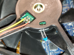
- PWM fan mod circuit installed, replacing the original thermistor.
Conclusion
After all this, I had a fan that would accept a PWM control signal and had at least some control over its fan speed. However, I later realized that the tachometer signal was not working, causing my motherboard to report that the fan had failed. At this point I didn’t really want to come up with another circuit (perhaps a Hall effect sensor) to sense the fan’s speed, so I simply took the easy way out and just disabled the warning in Intel Desktop Utilities 🙂 . I might revisit this mod sometime in the future if I need to do this again.
-

- Intel Desktop Utilities reporting that the fan I installed was slowed or stopped, as the tachometer signal was absent. Oops.
