Looking for my HDQ Utility to read out your own batteries? Click here!
UPDATE: Turns out the iPhone 3G and 3GS do have gas gauges! I will add them to my list as I find out more about them.
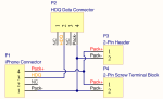
Each iPhone generation since the iPhone 4 iPhone 3G uses a TI gas gauge and uses the HDQ bus (iOS refers to this as the SWI [single-wire interface]) to communicate with the outside world. For more information about the HDQ protocol, click here.
I’ve noticed that many of the iPhone 5S and 5C batteries that can be purchased online are reusing iPhone 4 circuits, which will cause a significant decrease in gauge accuracy (proper parameters need to be programmed into the gas gauge, and that information is chemistry dependent), and the protection circuits in the iPhone 4 battery PCB will kick into overvoltage protection mode at 4.25 volts, less than the 4.3 volts that the iPhone 5 (and newer) batteries need to charge fully.
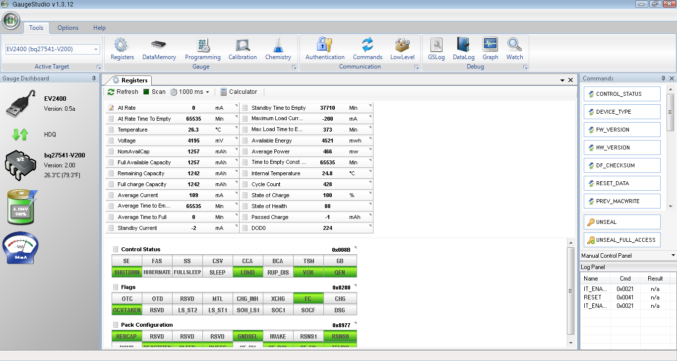
Because I have been unable to find a list of information of each battery generation, I’m making one myself. Because nobody else has dug this deep into the fuel gauges that the iPhone uses, I have to get this information experimentally (that is, by buying various batteries from online shops; the iPhone 5S battery has been very difficult to get, besides the fake ones I mentioned earlier).
So far I’m in need of an iPhone 3G (not the 3GS) battery, as well as all iPad batteries (or, if you have my program on hand, what model the battery is intended for, the fuel gauge device (eg. bq27541, bq27545), firmware version and designed capacity.
| Model | Gas Gauge | Firmware | Designed Capacity | Default Unseal Key? | Comments |
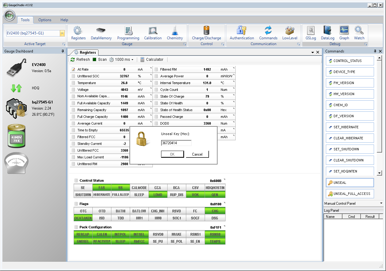
| iPhone 3G | bq27541 | ? | ? | Yes (0x36720414) | Need to acquire one of these. |
| iPhone 3GS | bq27541 | 1.17 | 1200 mAh | Yes (0x36720414) | Limited feature set. My utility will throw “No response” errors when reading this battery. |
| iPhone 4 | bq27541 | 1.25 | 1420 mAh | Yes (0x36720414) | |
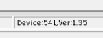
| iPhone 4S | bq27541 | 1.35 | 1430 mAh | Yes (0x36720414) | |
| iPhone 5 | bq27545 | 3.10 | 1430 mAh | No (0x52695035) | Many thanks to Yann B. for finding the unseal key! |
| iPhone 5S | bq27545 | 3.10 | 1550 mAh | No (0x84966864) | |
| iPhone 5C | bq27545 | 3.10 | 1500 mAh | No (0x84966864) | |
| iPhone 6 | sn27545-A4 (note 4) | 5.02 | 1751 mAh | No (0x65441236) | |
| iPhone 6 Plus | sn27545-A4 (note 4) | 5.02 | 2855 mAh | No (0x18794977) | |
| iPhone 6S | sn27546-A5 (note 5) | 6.01 | 1690 mAh | No (0x90375994) | |
| iPhone 6S Plus | sn27546-A5 (note 5) | 6.01 | 2725 mAh | No (0x11022669) | |
| iPhone SE | Unrecognized (note 6, 7) (A1141/0x1141) | 1.03 | 1560 mAh | No (unknown) | (See note 6) |
| Apple Watch (38mm) | sn27545-A4 | 5.02 | 235 mAh | No (0x09130978) | |
| Apple Watch (42mm) | sn27545-A4 | 5.02 | 245 mAh | No (unknown) | If anyone has one that reads “FULL ACCESS” in my program, please send it to me! 🙂 |
| iPad (3rd gen) | bq27541 | 1.35 | 11560 mAh | Yes (0x36720414) |
Notes:
- All known iPhone battery models use custom firmware, so not all of the features that the mainstream gas gauge models use are available. For example, none of these gauges will calculate the battery’s State of Health percentage (it is basically the percentage of the battery’s full charge capacity (it degrades with use) versus its designed capacity.
- The iPhone 5C’s battery label indicates a designed capacity of 1510 mAh, but the battery I’ve received indicates a capacity of 1550 mAh. As I have only been able to get one of these batteries that seem to be genuine, I will need to get more batteries of this type to confirm that this information is correct.
- The iPhone 5’s battery label indicates a designed capacity of 1440 mAh, but the fuel gauge reports 1430 mAh. The 5S battery reports 1550 mAh, but is labeled 1560 mAh. The 5C reports 1500 mAh, but is labeled 1510 mAh.
- The iPhone 6 and 6 Plus use a special firmware that is identified in TI’s battery software (except the very latest releases where such data was removed), and it has a very extensive feature set, and a lot of data logging features.
- The iPhone 6S/6S Plus use a firmware version similar to the iPhone 6/6 Plus, but with a newer chip and some features trimmed out. I’m reasonably confident that the chip is an sn27546-A5 but have no idea if it’s the official part designator.
- The iPhone SE battery seems to have a unique custom chip, but has gone back to a DFN-based package (similar to bq27541) rather than a BGA like the bq27545/546. It is marked “A1141” and does not respond to my HDQ adapter, only the official TI EV2300/EV2400. I have only one in my possession, so I am not 100% sure whether this is true for this series of batteries.
- Come to think of it, I might have been ripped off with the battery I received, and it could very well be that I just have a counterfeit that uses a non-TI gauge.