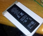
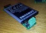
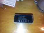
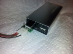
A while ago I mentioned purchasing a very cheap battery pack that obviously didn’t live up to expectations. However, I didn’t get a chance to write about a more capable power bank, the Mars RPB60. It was branded as a SoundLogic/XT power bank, and holds 4400 mAh of battery capacity, with two USB ports (one labeled for 1 amp and 2.1 amps) and a micro-USB power input.
The power bank
-
-
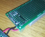
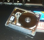
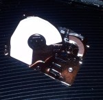
Power bank case
-
-
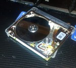
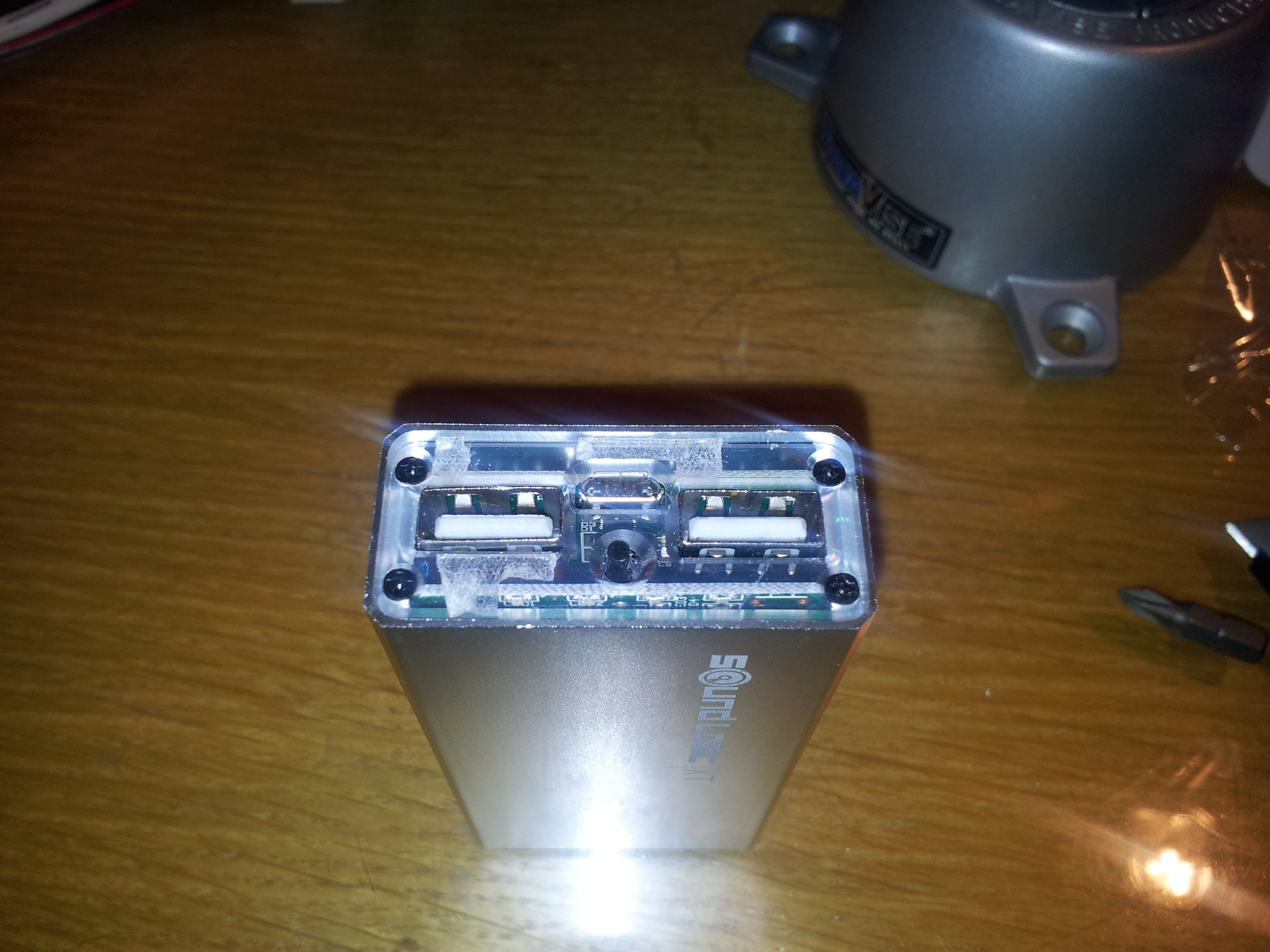
Front panel
-
-
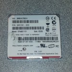
Rear panel
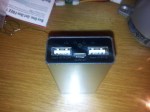
The power bank from the outside looks pretty nondescript, with two USB ports, a micro-USB input, a button and four blue LEDs. Initially it seemed that there wouldn’t be any easy way to open up the casing without damaging it, so I tried to pry away the plastic covers at the ends. Doing so revealed plastic plates held in with small Phillips screws. Disassembly from that point was a cinch.

Removing covers reveals hidden screws
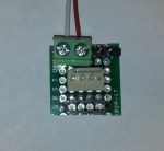
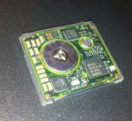
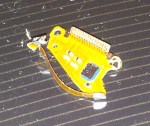
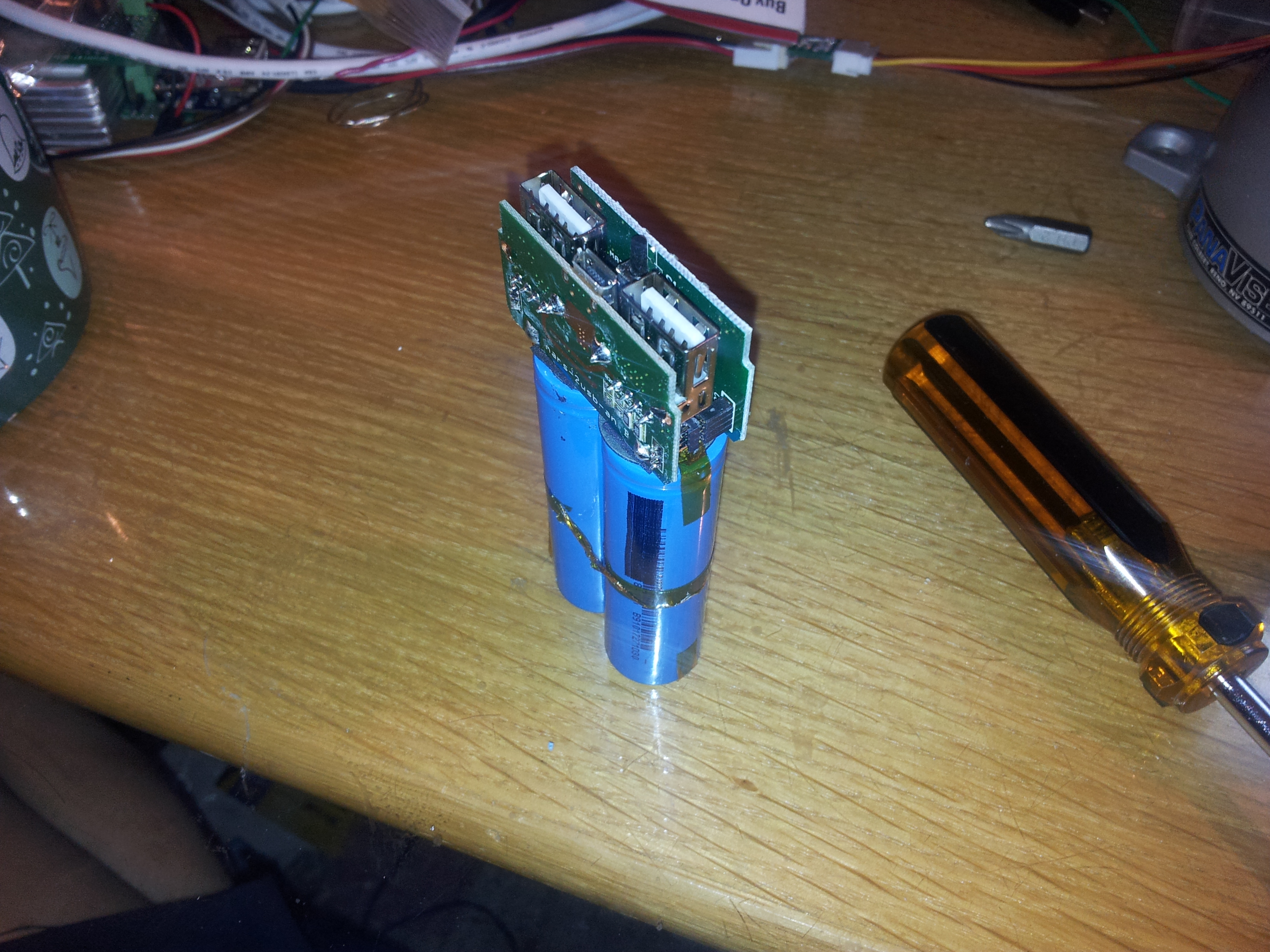
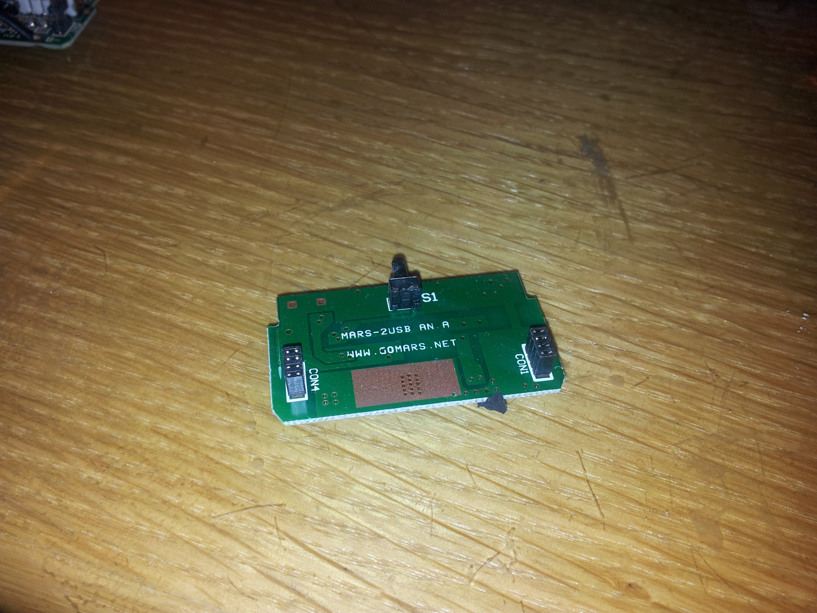
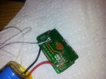
The PCB portion of the pack is of a stacked design. The two halves are connected with a set of small pin headers, with one side being the main DC-DC converter and USB output, and the other being the “gas gauge” and charging circuitry. The reason I put the phrase ‘gas gauge’ in quotes is that it’s only going by pure voltage thresholds, making it inaccurate when under load (like charging a phone and tablet, for example).
 The main microcontroller is an unmarked 14-pin SOIC (likely an OTP-based PIC clone) and a TP4056 Li-Ion charging IC. The DC-DC converter is a DFN package that I couldn’t find any data on, but from what I can tell it integrates the DC-DC converter control circuitry and the switching MOSFETs.

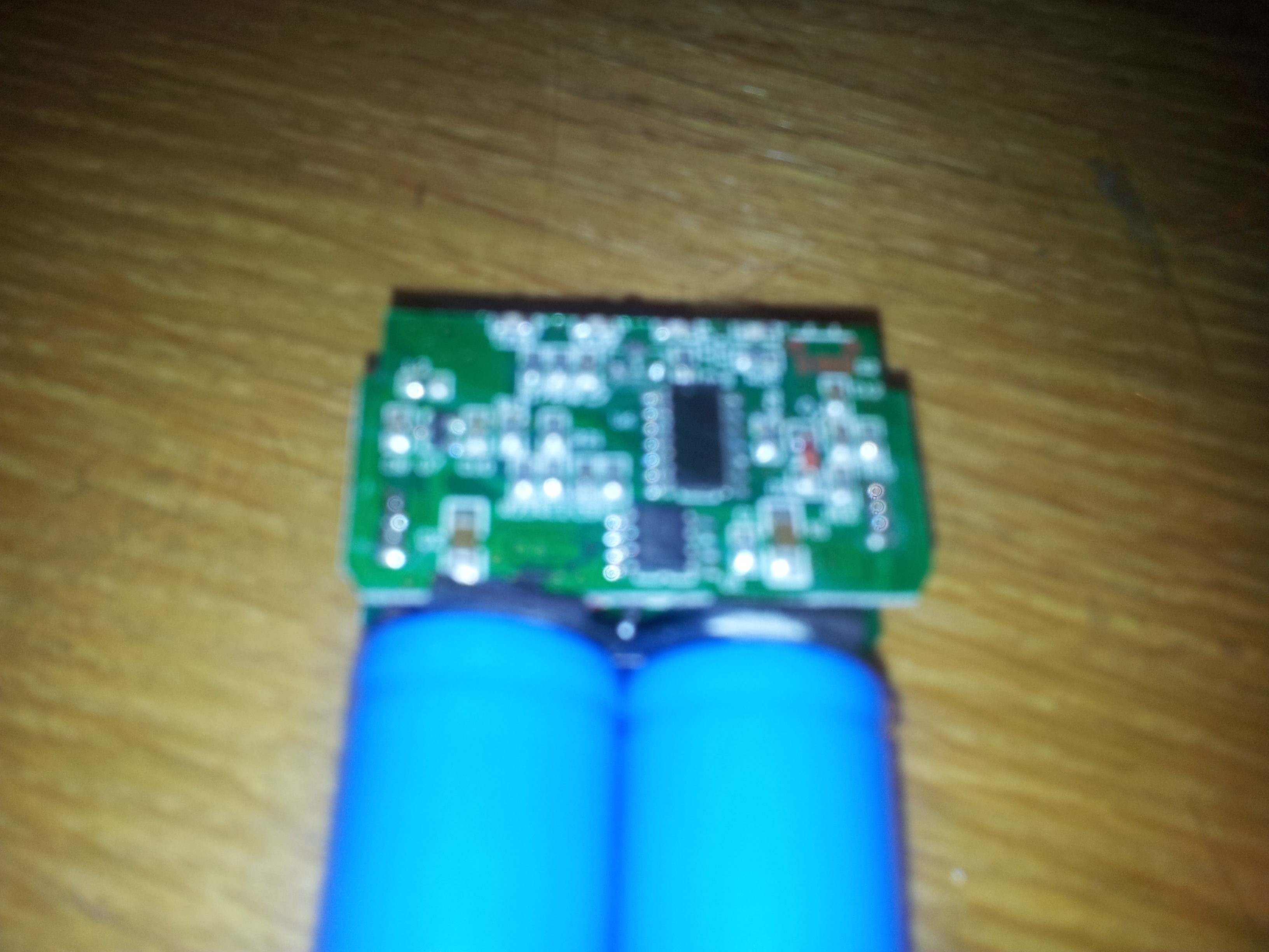
Blurry photo of microcontroller/charger PCB, taken with a potato for a camera. 😛
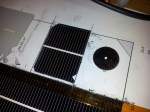
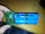
 Cells
Cells
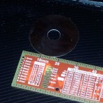
The cells themselves seemed to be of good quality, but the bastards at Mars decided to black out the branding and model number of the cells! However, I was unphased at their attempt to cover up what cells they were using. With a careful cleaning with flux remover and some Kimwipes, I found that this pack uses ATL INR18650 cells with a DW01-based protection circuit. These cells hold 2200 mAh each, and the INR prefix means that these are high-power cells intended to provide heavy output currents. This is desirable as a 10 watt load like an iPad would definitely put heavy strain on the batteries. Considering the good cells they used, I don’t understand why they’d want to hide the markings on the cells (and in a half-assed way too!)…
-
-
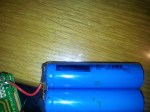
Cell part numbers weakly obfuscated
-
-
Part number revealed to be ATL INR18650
The initial capacity was at about 4800 mAh (greater than the rated capacity 😀 ) with an average ESR of about 63 milliOhms. However, after a dozen charge-discharge cycles, the capacity has decreased to 4630 mAh and has an average internal resistance of 190 milliOhms. I’ve got a feeling charge cycle endurance may be an issue with this battery pack. Time will tell…
Gas gauge hacking
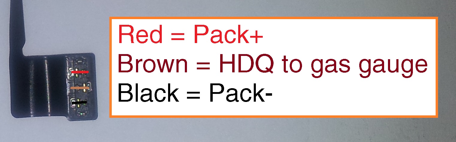
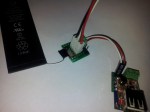
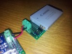
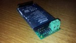
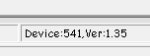
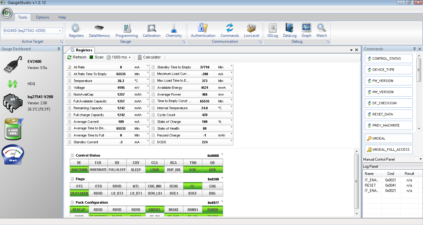
Since this battery pack didn’t have the gas gauge capabilities I wanted (voltage threshold-based gauging isn’t enough!), I decided to put in my own. I built a small bq27541-V200 gauge board with an external thermistor and current-sense resistor, using the breakout board itself to hold all the SMD passive components required for the gauge to function. The thermistor is taped to the cells to get an accurate temperature reading, and the current-sense resistor is attached in series between the cell’s negative terminal and the negative contact of the protection circuit.

Gas gauge chip added
This is where the hacking happens. I connected the I2C lines to the left USB port’s data lines. The voltage divider used for Apple devices is very high-resistance and makes for good I2C pullup resistors. The device still appears as a normal device charger but works just fine when the I2C signals are hidden behind the USB lines.
-
-
USB data lines hacked
-
-
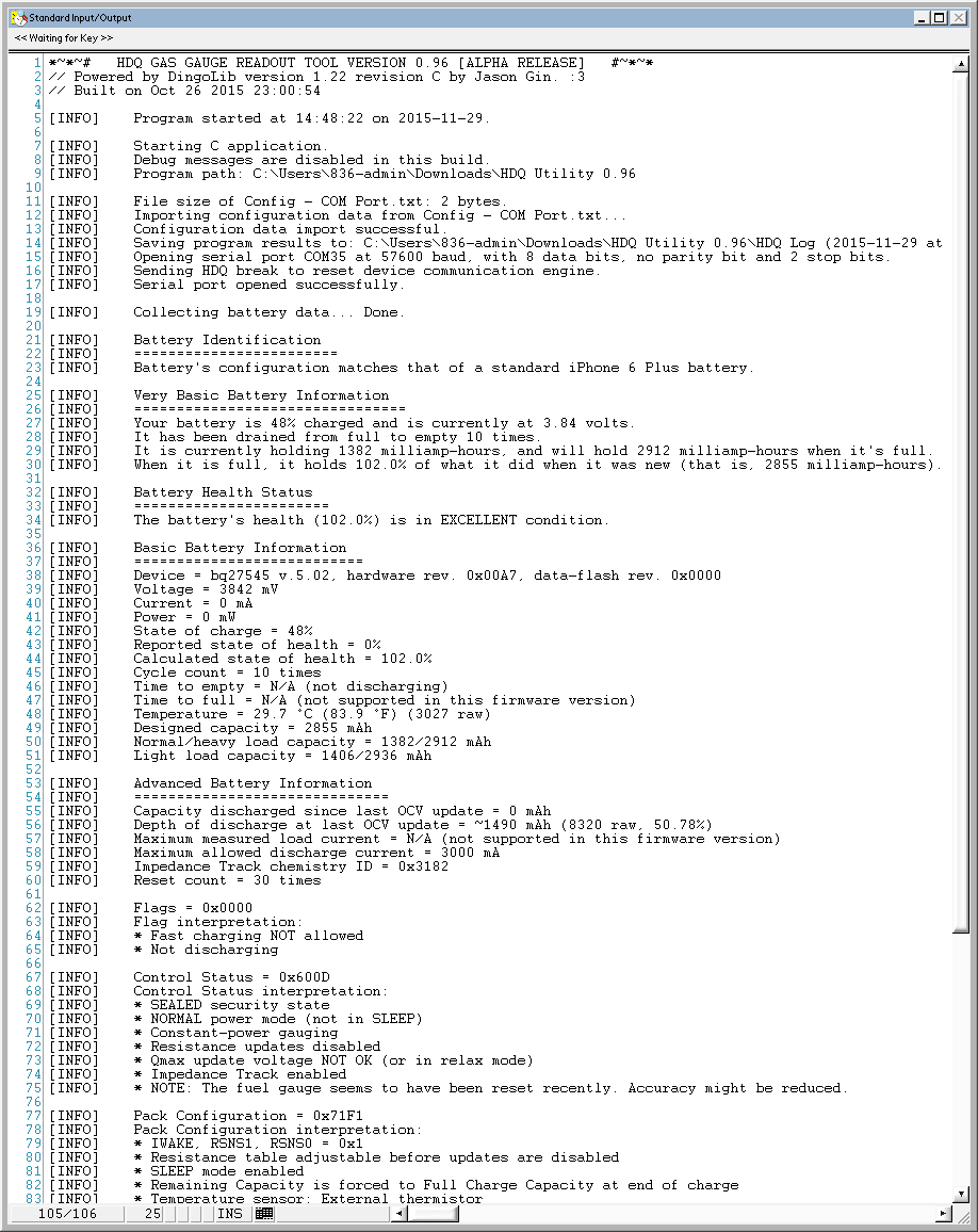
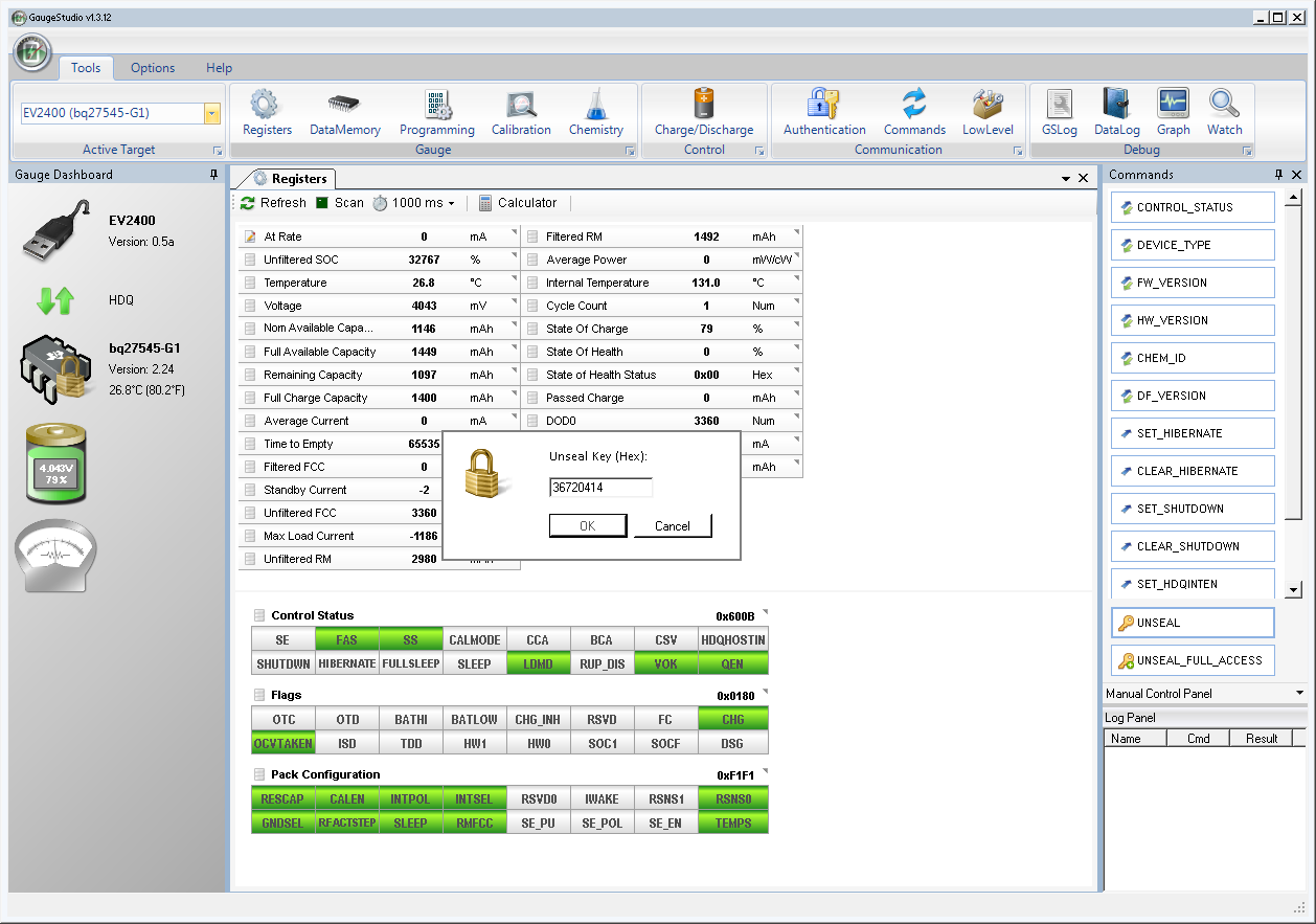
Adapter created to interface with EV2400 box
Quirks
However, the design for my gauge is definitely not the best one. I noticed that with heavy use (and not even one full discharge cycle), the gauge had reset 4 times without me knowing. Of course, I’m not expecting great performance from this gauge since it’s extremely susceptible to EMI (long wires looping around are just asking for trouble 🙂 ) in its current state. Given how I basically hacked this together in a matter of a few hours, it works well enough. Next up is to go into Altium Designer and make a proper gas gauge board with good EMI and RFI mitigation (and perhaps sell them on Tindie; the hobbyist community needs better gas gauges and stop being so paranoid about Li-Ion batteries).
Further testing showed that certain phones put pulses on the USB lines which has occasionally caused the bq27541 to crash and reset as well.
Additionally, I’ve noticed that the DC-DC converter circuit is quite inefficient. It has 5-7 mA of quiescent current draw and has about 60-80% efficiency. At a full charge, it will take only one month before all the charge is drained from the cells and the protection circuit disconnects the cells.
Future plans
Since this battery pack has a nicely built casing, I intend to gut the battery pack, design new PCBs inside with good DC-DC conversion, an Impedance Track-based fuel gauge, and an onboard microcontroller with some battery-logging capabilities (perhaps to an EEPROM or an SPI Flash ROM), accessible through the micro-USB port. I also plan to use some higher-capacity cells, like the 3400 mAh Panasonic NCR18650B.
If not, then at least I want to replace the microcontroller with one that will read the bq27541’s state of charge readings and display them on the LED bar graph.